
Low-cost haptic mouse implementations

a mouse and implementation technology, applied in the field of low-cost haptic devices, can solve the problems of limiting the haptic feedback effect, unable to significantly vary, and the tactile generation device of the gamepad may not be as suitable for other types of interface devices, so as to achieve the effect of low-cost haptic feedback capability

Inactive Publication Date: 2008-09-09
IMMERSION CORPORATION
View PDF288 Cites 85 Cited by
  • Summary
  • Abstract
  • Description
  • Claims
  • Application Information

AI Technical Summary

Benefits of technology

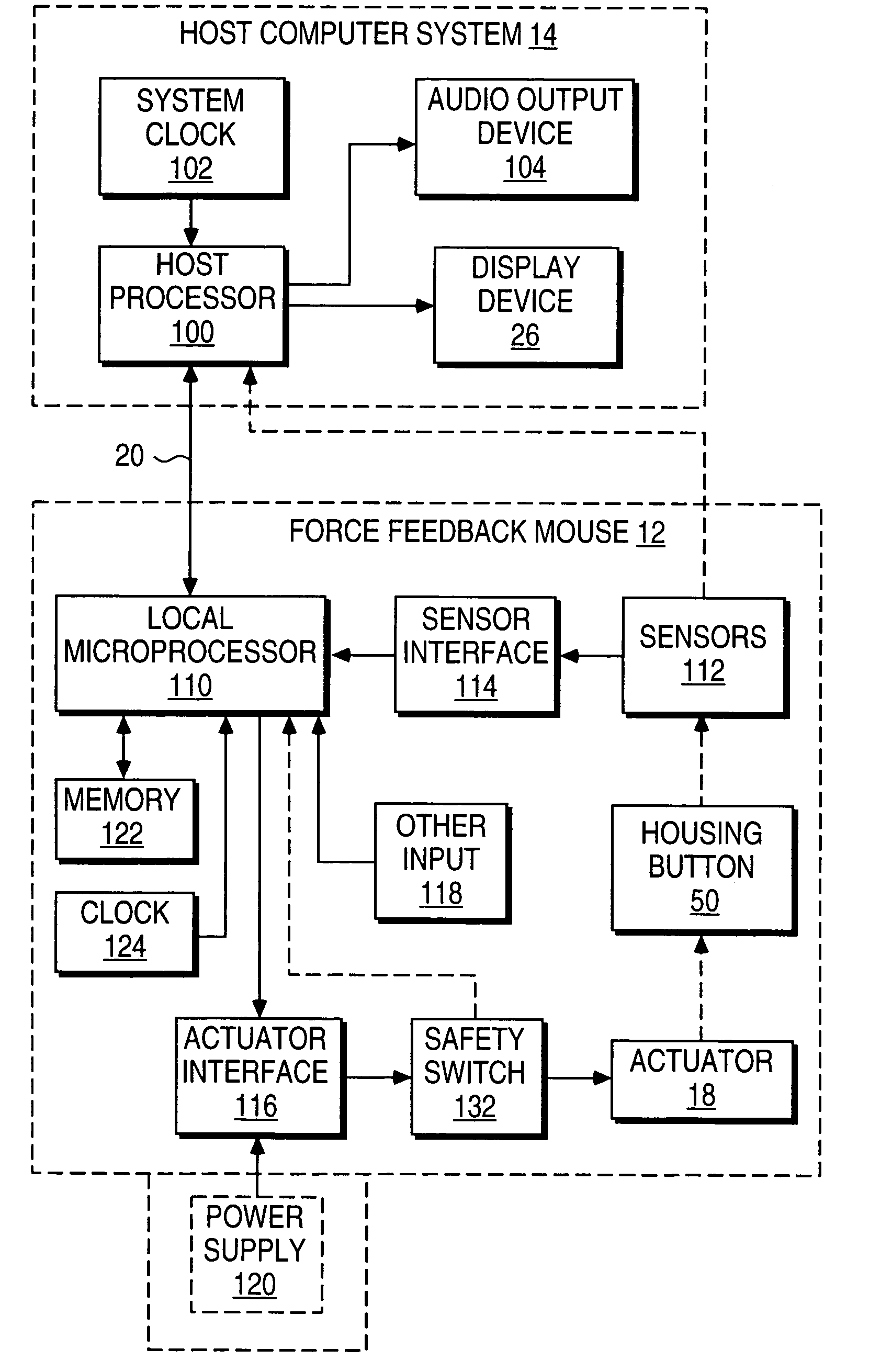
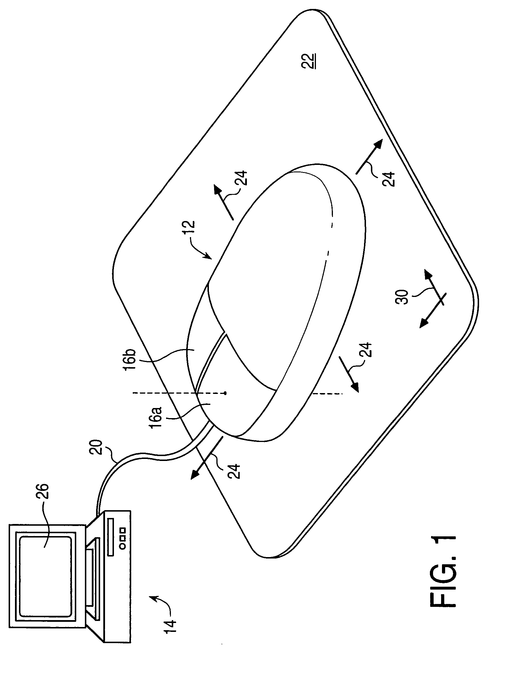
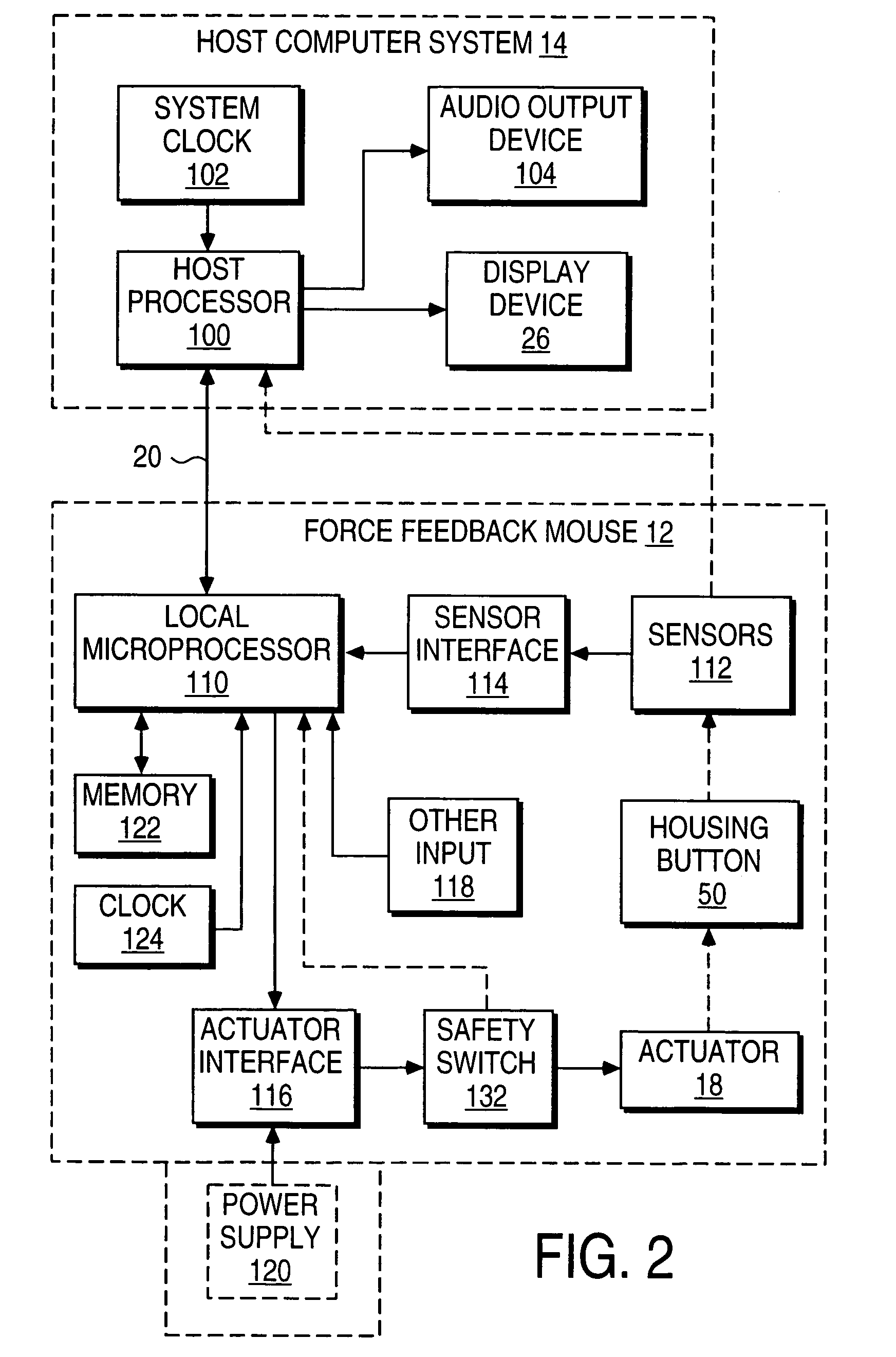
[0007]The present invention is directed to providing low-cost haptic feedback capability to a mouse interface device and other interface devices that communicate with a host computer or controller. The embodiments disclosed herein allow haptic sensations to be output by devices that do not require significant design changes to existing interface devices.
[0013]The present invention advantageously provides embodiments for a low-cost haptic feedback device that can output a variety of haptic sensations. The actuators can be implemented in existing interface devices with relatively little added expense. The presented features allow precision in the control of haptic sensations and a compelling range of sensations to be experienced by the user.

Problems solved by technology

One problem with these currently-available implementations of haptic feedback devices is that the vibrations or other haptic sensations that these implementations produce are very limited and cannot be significantly varied.
In addition, gamepad tactile generation devices may not be as suitable for other types of interface devices, in particular mouse interfaces or other similar position control input devices.
The prior art devices also severely limit the haptic feedback effects which can be experienced by a user of these devices.

Method used


Image

  • Low-cost haptic mouse implementations
  • Low-cost haptic mouse implementations
  • Low-cost haptic mouse implementations

Examples


embodiment 200

[0055]In embodiment 200, the motor 208 is positioned such that the eccentric mass 212 rotates in approximately the y-z plane, where the shaft of the motor extends parallel to the x-axis. Thus, the inertial forces output by the rotation of the mass are along the y- and z-axes. If the mass is rotated quickly enough and / or if the inertial forces on the housing are of high enough magnitude, the mouse may be moved or vibrated along the y-axis and the portion of the forces output in the y-axis may cause a controlled object, such as a displayed cursor, to change its y position in a graphical environment in response to motor activation. If this effect is undesired, it can be alleviated in some embodiments by providing a selective disturbance filter, as described in U.S. Pat. No. 6,020,876 and incorporated herein by reference in its entirety.

[0056]The embodiment 200 can produce strong forces to the user if the mass 212 is rotated quickly. In some embodiments, forces output to the user can be...

embodiment 220

[0058]FIG. 3b is a perspective view of a mouse device 220 providing tactile sensations to a user with an eccentric rotating mass. Embodiment 220 is similar to mouse 200 described above, and can include a lower base portion 222, a ball (or other type) sensor 224, a mouse wheel 226, circuits (not shown), and other standard components. A rotary motor 228 can be coupled to the base 222, where a rotary shaft 230 of the motor is coupled to an eccentric mass 232 positioned so that the center of mass of the mass 232 is offset from the center of rotation of the shaft 230. A cover portion 234, shown in dashed lines, can be normally positioned over the base portion 222.

[0059]Embodiment 220 differs from embodiment 200 in that the motor 228 is positioned such that the shaft 230 is parallel to the z-axis and rotates the eccentric mass 232 in the x-y plane. The inertial sensations are similar to those produced by embodiment 220, except that the forces are provided in the x-y plane. If the inertial...

embodiment 250

[0062]Furthermore, embodiment 250 allows tactile sensations to be output on the button 256. When the eccentric mass 254 is rotated to the top of its rotational range, i.e., its closest position to the magnet 258, the mass magnetically influences the button 256 by attracting the magnet 258 toward the mass 254. For example, the mass 254 can be made of a metal, such as iron or steel, that magnetically interacts with the magnet 258. If the magnetic attraction force is strong enough, it may cause the button 256 to move in the direction toward the mass 254; however, the forces are preferably made sufficiently weak to not cause the button switch to close. This allows the user to press the button when desired with little or no interference from forces output in the button's degree of freedom. For example, the button travel range can be made large enough and can include a sensor to detect button position, so that when the button reaches a position near to the button switch, the forces are re...


PUM


Abstract

Low-cost haptic interface device implementations for interfacing a user with a host computer. A haptic feedback device, such as a mouse or other device, includes a housing physically contacted by a user, and an actuator for providing motion that causes haptic sensations on the device housing and / or on a movable portion of the housing. The device may include a sensor for detecting x-y planar motion of the housing. Embodiments include actuators with eccentric rotating masses, buttons having motion influenced by various actuator forces, and housing portions moved by actuators to generate haptic sensations to a user contacting the driven surfaces.

Description

CROSS REFERENCE TO RELATED APPLICATIONS[0001]This application is a continuation of U.S. application Ser. No. 09 / 759,780, filed Jan. 12, 2001, now U.S. Pat. No. 6,717,573 which claims the benefit of U.S. Provisional Application No. 60 / 176,108, filed Jan. 14, 2000, entitled “Low-Cost Haptic Mouse Implementations;” U.S. application Ser. No. 09 / 759,780 is a continuation-in-part of U.S. patent application No. 09 / 253,132, filed Feb. 18, 1999, now U.S. Pat. No. 6,243,078; Ser. No. 09 / 456,887, filed Dec. 7, 1999, now U.S. Pat. No. 6,211,861; and Ser. No. 09 / 563,783, filed May 2, 2000, now U.S. Pat. No. 6,353,427, which is a continuation of application Ser. No. 09 / 103,281, filed Jun. 23, 1998, now U.S. Pat. No. 6,088,019, all of which are incorporated by reference herein in their entirety.BACKGROUND OF THE INVENTION[0002]The present invention relates generally to haptic feedback interface devices for use with a computer, and more particularly to low-cost haptic devices producing tactile sens...

Claims


Application Information

Patent Timeline
IPC IPC(8): G09G5/00G06F3/033G09G5/08A63F13/06G06F3/00G06F3/01H04L29/08
CPCA63F13/06G06F3/016G06F3/03543A63F2300/1037A63F2300/1043A63F2300/1062H04L67/125G06F2203/014A63F2300/8017A63F13/245A63F13/803A63F13/285A63F13/24
Inventor SHAHOIAN, ERIK J.ROSENBERG, LOUIS B.
Owner IMMERSION CORPORATION
Learn More