Cryostat configuration with cryocooler

a cryostat and configuration technology, applied in the field of cryostat configuration, can solve the problems of reducing production costs, the need for further neck tube installation to no longer meet, and achieve the effect of reducing heat inpu

Inactive Publication Date: 2007-04-26
BRUKER BIOSPIN
View PDF10 Cites 50 Cited by
  • Summary
  • Abstract
  • Description
  • Claims
  • Application Information

AI Technical Summary

Benefits of technology

[0025] Moreover, at least one suspension tube of the cryocontainer, which is connected to the neck tube in a heat-conducting manner, may additionally be connected to an additional line or exclusively to the additional line which is in thermal contact with the neck tube and terminates in the cryocontainer, wherein a shut-off device and / or a pump may be inserted in the additional line. The additional line does not connect the cryocontainer to the inside of the neck tube but is guided past it, forming a gas flow through the suspension tube and the additional line and back into the cryocontainer. The ascending gas thereby accepts heat from the wall of the suspension tube, cooling it, and being cooled again in the additional line in that region where it is connected to the neck tube. This reduces the heat input into the cryocontainer via the suspension tube(s).
[0026] In an alternative embodiment of the inventive cryostat configuration, the cryocontainer is connected to the end of the neck tube, which is at ambient temperature, via at least one fluid line which is guided through the outer shell of the cryostat configuration, wherein the outer shell, the at least one cryocontainer, the neck tube and the at least one fluid line define an evacuated space, and wherein a rapid-action valve and a shut-off device are integrated in the fluid line in the region between the outer shell and the neck tube. This fluid line can guide cryogen from the cryocontainer into the neck tube even in cryostat configurations which are not suspended from suspension tubes.

Problems solved by technology

Moreover, the neck tube and further neck tube installations must no longer meet the strict guidelines and safety regulations for pressure containers imposed by the authorities, which reduces production costs.

Method used


Image

  • Cryostat configuration with cryocooler
  • Cryostat configuration with cryocooler
  • Cryostat configuration with cryocooler

Examples


Embodiment Construction

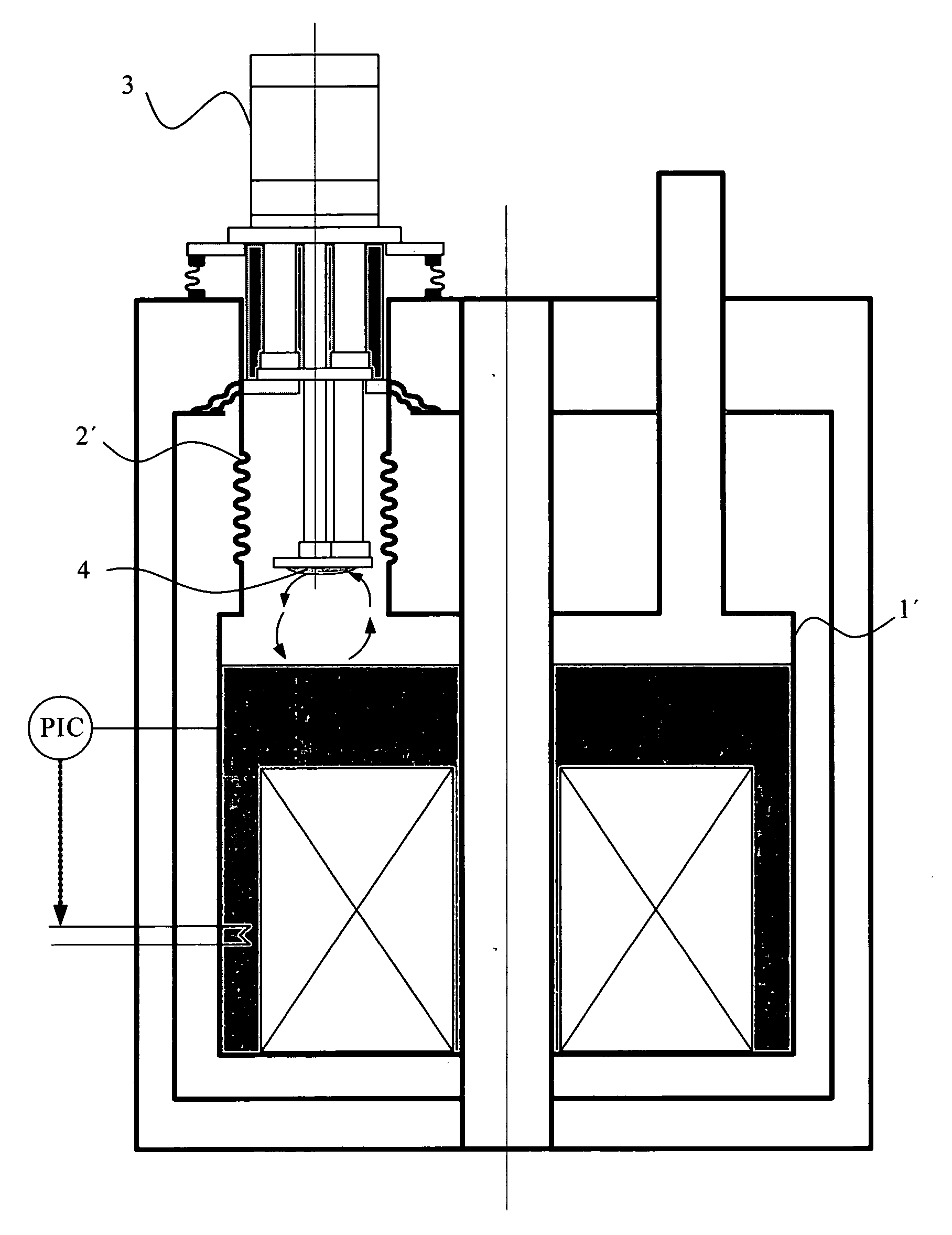
[0048]FIG. 1 shows a cryostat configuration comprising a superconducting magnet coil 26 with a neck tube 2′ which is open towards a cryocontainer 1′, is partially formed as a bellows, and contains a two-stage cold head 3 of a cryocooler. The cryogen 4 which is liquefied at the cold head 3 drips directly into the cryocontainer 1′ from which the cryogen that evaporates due to heat input into the cryocontainer 1′ rises into the neck tube 2′ to be reliquefied by the cold head 3. In case the magnet quenches, the pressure in the cryocontainer 1′ and also in the neck tube 2′ rapidly increases, such that safe installation or removal of the cold head 3 during operation of the cryostat configuration cannot be ensured. Since the neck tube 2′ is also subjected to the increased pressure in case of a quench, it must be designed to bear the high mechanical loads during a quench. Moreover, the neck tube 2′ and further neck tube installations must meet stricter guidelines and safety regulations impo...


PUM


Abstract

A cryostat configuration for keeping cryogenic fluids in at least one cryocontainer, comprising an outer shell and a neck tube containing a cold head of a cryocooler, wherein the coldest cold stage of the cold head is disposed in a contact-free manner relative to the neck tube and the cryocontainer, and wherein a cryogenic fluid is located in the neck tube, is characterized in that the neck tube is disposed between the outer shell and a cryocontainer and/or the radiation shield, the neck tube is closed in a gas-tight manner at the end facing the cryocontainer and/or the radiation shield, the neck tube is coupled to the cryocontainer and/or a radiation shield disposed between the cryocontainers or a cryocontainer and the outer shell, via a connection having a good thermal conductivity, the neck tube comprising a fill-in device at an end located at ambient temperature. This permits efficient heat transfer between the cryocooler and the cryocontainer with little vibration, while simultaneously ensuring great safety during maintenance work without discharging the magnet.

Description

[0001] This application claims Paris Convention priority of DE 10 2005 029 151.1 filed Jun. 23, 2005 the complete disclosure of which is hereby incorporated by reference. BACKGROUND OF THE INVENTION [0002] The invention concerns a cryostat configuration for keeping cryogenic fluids in at least one cryocontainer, comprising an outer shell and a neck tube in which a cold head of a cryocooler is installed, wherein at least the coldest cooling stage of the cold head of the cryocooler is disposed in such a manner that it does not contact the neck tube and the cryocontainer, wherein a cryogenic fluid is contained in the neck tube. [0003] A cryostat configuration of this type is disclosed in US 2002 / 0002830 A1. [0004] In cryostat configurations for keeping liquid cryogens, which are used e.g. in nuclear magnetic resonance (NMR) measuring apparatus, a superconducting magnet coil system is disposed in a first container containing liquid cryogen, usually liquid helium, which is surrounded by ...

Claims


Application Information

Patent Timeline
Patent Type & Authority Applications(United States)
IPC IPC(8): F25B9/00F17C5/02F25B19/00
CPCF17C2203/0312F17C2203/0629F17C2223/0161F17C2223/033F17C2227/0353F17C2227/0372F17C2227/0381F17C2265/032F17C2270/0527F25B9/10F25B9/145F25B2309/1428F25B2400/17F25D19/006G01R33/3815
Inventor BOESEL, JOHANNESMEIER, URSKRAUS, ANDREASMRAZ, BEAT
Owner BRUKER BIOSPIN
Why Eureka
Try Eureka