Engine supercharging system

a supercharging system and engine technology, applied in the direction of machines/engines, electrical control, separation processes, etc., can solve the problems of small supercharging function, inability to achieve output improvement effect at the time of high load at high speed, and inverse reduction of outpu

Inactive Publication Date: 2003-04-24
HITACHI LTD
View PDF0 Cites 52 Cited by
  • Summary
  • Abstract
  • Description
  • Claims
  • Application Information

AI Technical Summary

Problems solved by technology

In the aforementioned prior art, a problem as indicated below arises.
However, on the other hand, at the time of high speed running, exhaust gas is excessively supplied to the small turbine and if it is left alone, the output is inversely reduced due to an increase in the exhaust pressure, so that to prevent it, exhaust gas is discharged into the exhaust tube as it is from the second valve not via the supercharger.
As a result, at the time of high speed running, the supercharging function can be little fulfilled and the original role of the turbo engine, for example, the output improvement effect at the time of high load at high speed cannot be obtained.
Therefore, even if the turbine having a comparatively large capacity of the second supercharging mechanism is manufactured with comparatively low accuracy such that the clearance between the turbine and the housing thereof is 1.5 times or more of the clearance between the turbine and the housing of the first supercharging mechanism, the engine can be supercharged sufficiently.
In this case, generally, when the small capacity turbine is used, the exhaust pressure is increased and the fuel expense is increased, though the response is high, while when the large capacity turbine is used, the fuel expense is inversely decreased, though the response is inferior to that of the small capacity turbine.
As mentioned above, generally, when the small capacity turbine is used, the response at the time of low speed running is improved, while at the time of high speed running, the exhaust pressure is increased and the fuel expense is increased, and when the large capacity turbine is used, the response at the time of low speed running is inferior to that of the small capacity turbine.

Method used


Image

  • Engine supercharging system
  • Engine supercharging system
  • Engine supercharging system

Examples


Embodiment Construction

[0048] The embodiments of the present invention will be explained hereunder with reference to the accompanying drawings.

[0049] The first embodiment of the present invention will be explained by referring to FIGS. 1 to 14.

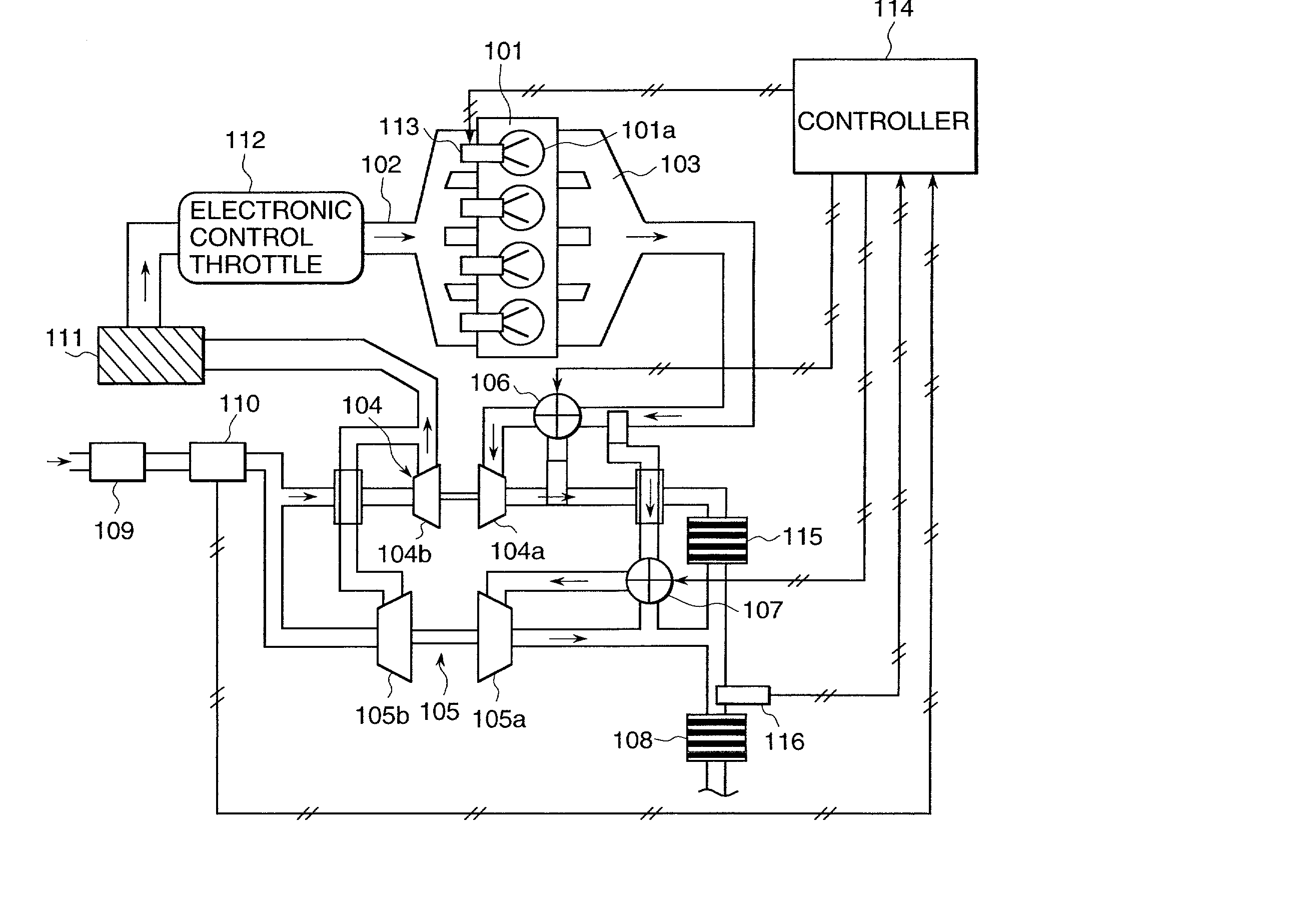
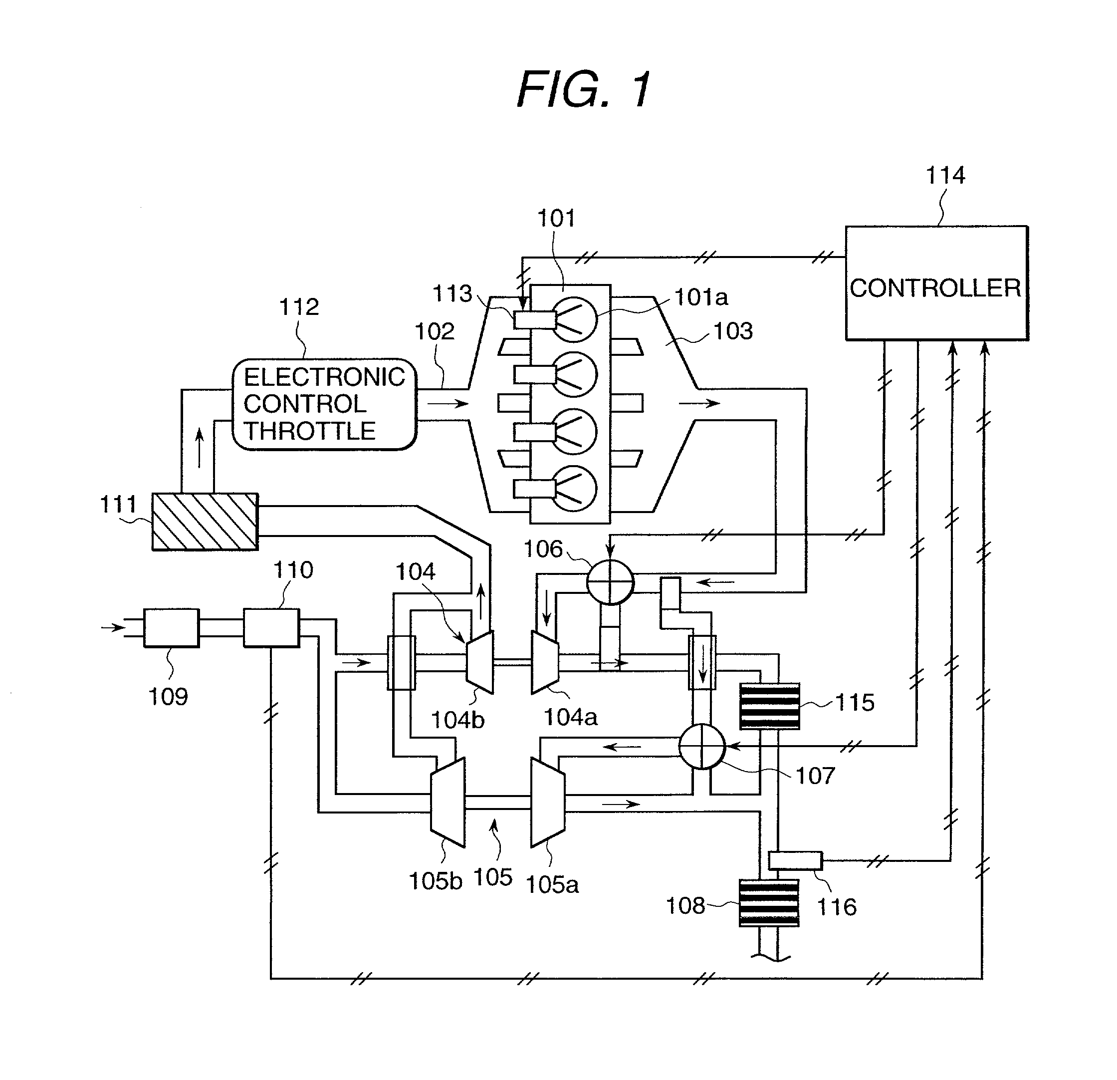
[0050] FIG. 1 is a system block diagram showing the whole rough constitution of the engine supercharging system of this embodiment. In FIG. 1, a fuel jet valve 113 is attached to an engine 101 so as to directly jet fuel to a cylinder 101a of the engine 101.

[0051] In the engine 101, in the air intake process, the air intake valve (not shown in the drawing) opens and the piston (not shown in the drawing) moves down and inhales air. In this case, when homogeneous combustion is to be carried out, fuel is jetted at this timing and mixing of fuel and air in the cylinder is sufficiently expedited via the nest compression process, so that the air use rate is high and high torque can be generated. Then, in the compression process, the air intake valve is closed, and the pist...


PUM


Abstract

The present invention is intended to sufficiently fulfill the supercharging function at the time of either of low speed running of the engine and high speed running and realizing output improvement or fuel expense reduction. The present invention has the engine 101 having the jet mechanism for directly jetting fuel into the cylinder 101a, the first turbo supercharger 104 for supercharging the engine 101 at the time of low speed rotation, the second turbo supercharger 105 for supercharging at the time of high speed rotation, the first and second exhaust control valves 106 and 107 for selecting exhaust paths relating to the first and second turbo superchargers 104 and 105 and controlling the exhaust gas flow rate, and the controller 114 for controlling the switching operation of the exhaust control valves 106 and 107 so as to realize lamination combustion or homogeneous combustion using the first and second turbo superchargers 104 and 105 according to the operation conditions of the engine 101.

Description

[0001] 1. Field of the Invention[0002] The present invention relates to an engine supercharging system for supercharging an engine which directly jets fuel into a cylinder and burns by ignition.[0003] 2. Prior Art[0004] Conventionally, for example, an internal-combustion engine with a turbo supercharger for supercharging intake air by a turbo supercharger composed of a compressor connected to a turbine installed in an exhaust path and a turbine installed in an air intake path is widely known.[0005] In recent years, an engine for directly jetting fuel into a cylinder has been widely used. As an engine that the output of this direct jet engine is improved by supercharging, for example, the engine supercharging system described in Japanese Application Patent Laid-open Publication No. Hei 10-89106 is available.[0006] This engine supercharging system has a jet mechanism for directly jetting fuel into the cylinder, an engine having a first exhaust valve and a second exhaust valve in each ...

Claims


Application Information

Patent Timeline
Patent Type & Authority Applications(United States)
IPC IPC(8): F02D23/00F02B75/12F02B37/12F02D23/02F02D43/00F02D41/02F02B37/18F01N3/24B01D53/94F02B37/007F01N3/20F02D45/00F02B37/00
CPCY02T10/123F02B37/18F01N3/2053F02B37/007F02B37/12Y02T10/26F01N3/2006Y02T10/144F02B2075/125Y02T10/12
Inventor YAMAGUCHI, JUN'ICHIONISHI, KOJIABO, MATSUHARU
Owner HITACHI LTD
Why Eureka
Try Eureka