Quick change spindle

a spindle and spindle technology, applied in the direction of control mechanisms, turning machine accessories, program control, etc., can solve the problems of increasing the cost of manual actuation of the mechanism, reducing the efficiency of processes, so as to reduce the potential for human error, reduce the time of tool changeover, and improve the effect of assembly cycle times

Inactive Publication Date: 2009-06-04
CINETIC AUTOMATION
View PDF6 Cites 56 Cited by
  • Summary
  • Abstract
  • Description
  • Claims
  • Application Information

AI Technical Summary

Benefits of technology

[0004]In accordance with the present invention, an automated tool includes a quick change spindle assembly. In another aspect of the present invention, the quick change spindle includes an attachment assembly for interchangeable fastener drivers. A further aspect of the present invention employs a holder assembly with an automated release member to actuate a drive member in a spindle assembly thereby causing a retainer to uncouple a fastener driver with the spindle. Still another aspect of the present invention utilizes a restoring member to return a drive member back to an extended position causing the retainer to couple a fastener driver with a spindle. In yet another aspect of the present invention, a system can perform multiple tasks using multiple fastener drivers without manual intervention to change fastener drivers.
[0005]The present quick change spindle is advantageous over previous devices in that the present invention significantly improves assembly cycle times. Automating the process of changing fastener drivers decreases tool changeover times and reduces the potential for human error. Furthermore, the present invention facilitates easier removal and attachment of fastener drivers without the disadvantage of misplacing drivers during or after changes. Further areas of applicability will become apparent from the description provided herein. It should be understood that the description and specific examples are intended for purposes of illustration only and are not intended to limit the scope of the present disclosure. Additional features and advantages of the present invention will be shown and described with reference to the following description and appended figures.

Problems solved by technology

Manually changing fastener drivers, however, often decreases the efficiency of processes, and the sequence of tasks performed by a particular system may require multiple fastener drivers or multiple tool systems, thus further complicating and slowing the assembly cycle and / or increasing expense.
However, each also requires manual actuation of the mechanism.

Method used


Image

  • Quick change spindle
  • Quick change spindle
  • Quick change spindle

Examples


Embodiment Construction

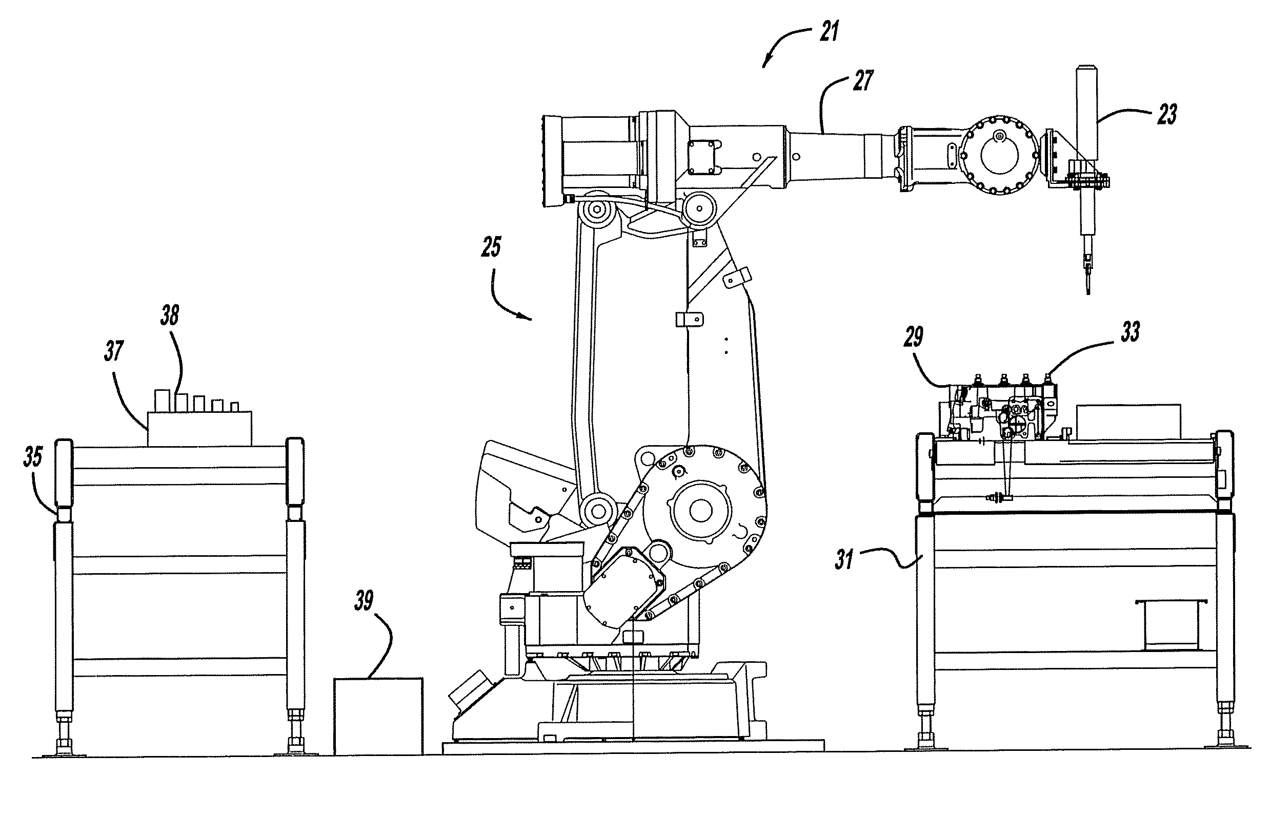
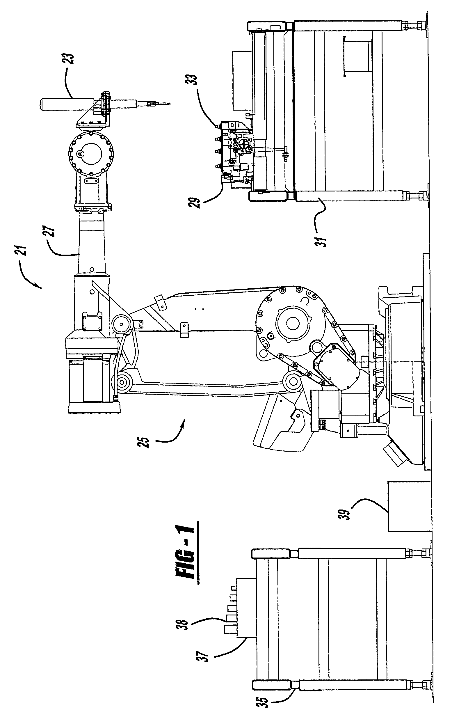
[0020]FIG. 1 shows a work station 21 in an assembly plant that employs the preferred embodiments of a quick change spindle assembly 23. An articulated or gantry robot 25 has an arm 27 that holds spindle assembly 23. Robot arm 27 moves spindle assembly 23 into various positions to perform operations on a work piece 29 located on a conveyor 31. An exemplary conveyor is disclosed in U.S. Pat. No. 6,705,454, entitled “Accumulating Power Roll Conveyor System” which issued to Fishaw et al. on Mar. 16, 2004, which is incorporated by reference herein. The work piece 29 is preferably a powertrain component such as an automotive vehicle engine block but may alternately be another component having fasteners 33. Robot arm 27 also moves spindle assembly 23 to a stand 35 where a holder assembly 37 accommodates multiple fastener drivers 38. A computer microprocessor 39 or other programmable controller includes software instructions which control robot 25, spindle assembly 23, and holder assembly 3...


PUM

PropertyMeasurementUnit
forceaaaaaaaaaa
applied forceaaaaaaaaaa
timeaaaaaaaaaa

Abstract

An automated tool includes a quick change spindle assembly. In another aspect of the present invention, the quick change spindle includes an attachment assembly for interchangeable fastener drivers. A further aspect of the present invention employs release member to actuate a drive member in the spindle assembly causing a retainer to uncouple a fastener driver with the spindle.

Description

BACKGROUND AND SUMMARY OF THE INVENTION[0001]The present invention relates to automated tool systems having interchangeable fastener drivers and more particularly to a device and method for automating the process of changing fastener drivers on an automated tool system.[0002]In many assembly processes, a tool system may need to perform several different operations on fasteners of different geometries, each requiring a unique fastener driver. Past tool systems required manual intervention to change a fastener driver to perform a new operation or multiple separate drivers were employed. Manually changing fastener drivers, however, often decreases the efficiency of processes, and the sequence of tasks performed by a particular system may require multiple fastener drivers or multiple tool systems, thus further complicating and slowing the assembly cycle and / or increasing expense. As assembly cycle times continue to improve, an automated tool system is needed to decrease the time to chan...

Claims


Application Information

Patent Timeline
Patent Type & Authority Applications(United States)
IPC IPC(8): B25B23/00B25J18/00B25B13/06B23P19/04G05B19/00
CPCB23B31/1071Y10T29/49948B23B2270/22B23P19/06B25B23/0035Y10T483/1793Y10T403/592Y10T279/1091Y10T279/17829Y10T483/1736Y10T29/53Y10T279/1045Y10T403/604Y10T483/17Y10T74/20305Y10T403/593B23B2260/136B21J15/10B25J15/0416B25J15/0019
Inventor HATHAWAY, THOMAS J.HAGEMAN, MICHAEL A.GRIMES, JAMES W.
Owner CINETIC AUTOMATION
Why Eureka
Try Eureka