Bit line control circuit for semiconductor memory device
a control circuit and memory device technology, applied in the field of semiconductor memory devices, can solve the problems of difficult to amplify a large amount of cell data, and achieve the effect of preventing the voltage level of a vcore terminal from rapidly increasing
- Summary
- Abstract
- Description
- Claims
- Application Information
AI Technical Summary
Benefits of technology
Problems solved by technology
Method used
Image
Examples
first embodiment
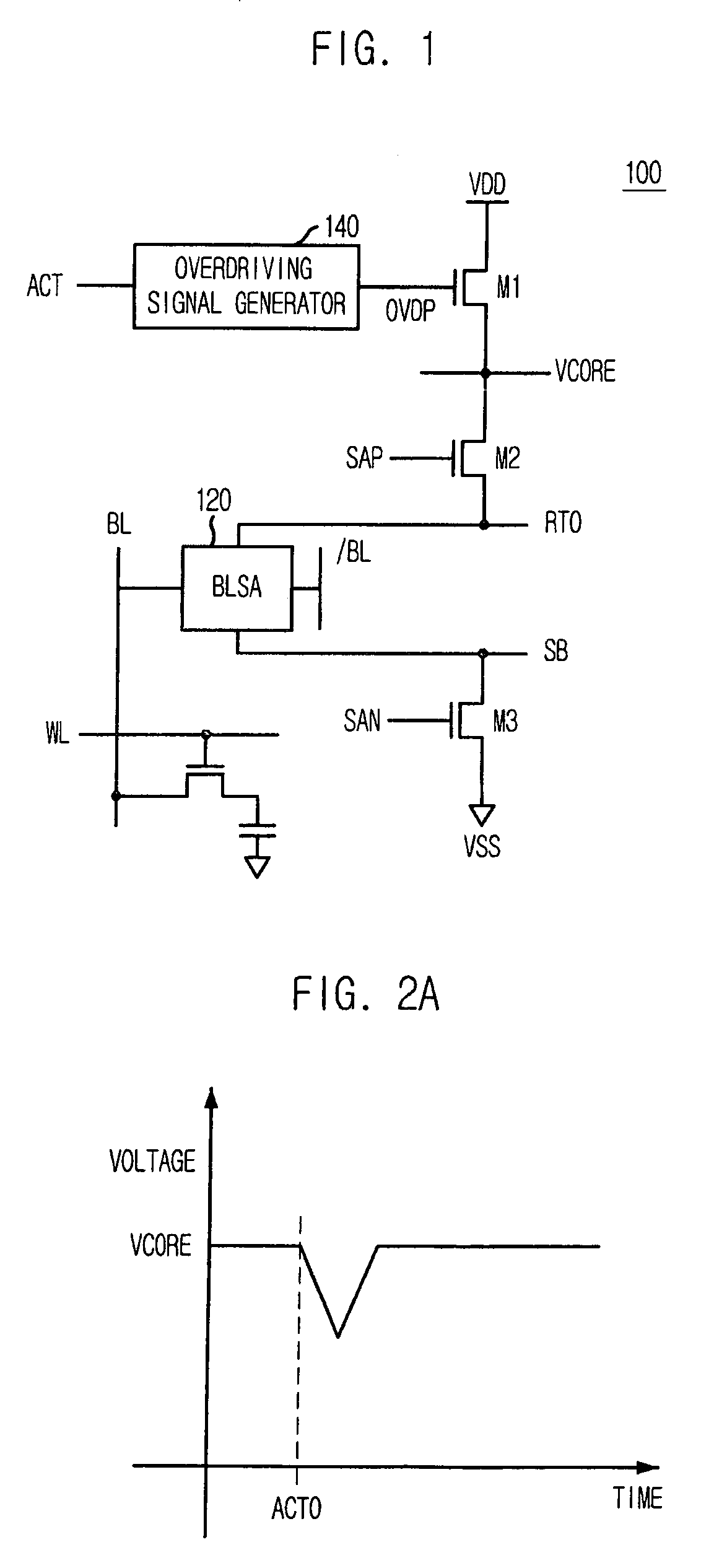
[0017]FIG. 1 is a schematic diagram of a BLSA control circuit in accordance with the present invention.
[0018]Referring to FIG. 1, the bit lines sense amplifier control circuit 100 includes a pull-up voltage line RT0 and a pull-down voltage line SB, each coupled to a BLSA 120. Also, the bit line sense amplifier includes a plurality of driver transistors M1, M2 and M3 for driving the voltage lines RT0 and SB to a specific voltage.
[0019]Specifically, a second driver transistor M2 drives the pull-up voltage line RT0 to a voltage of the VCORE terminal in response to a pull-up driving control signal SAP, and a third driver transistor M3 drives the pull-down voltage line SB to a ground voltage VSS in response to a pull-down driving control signal SAN. A first driver transistor M1 drives the VCORE terminal to an external voltage VDD in response to an overdriving signal OVDP.
[0020]An overdriving signal generator 140 generates the overdriving signal OVDP in response to an active command ACT. ...
second embodiment
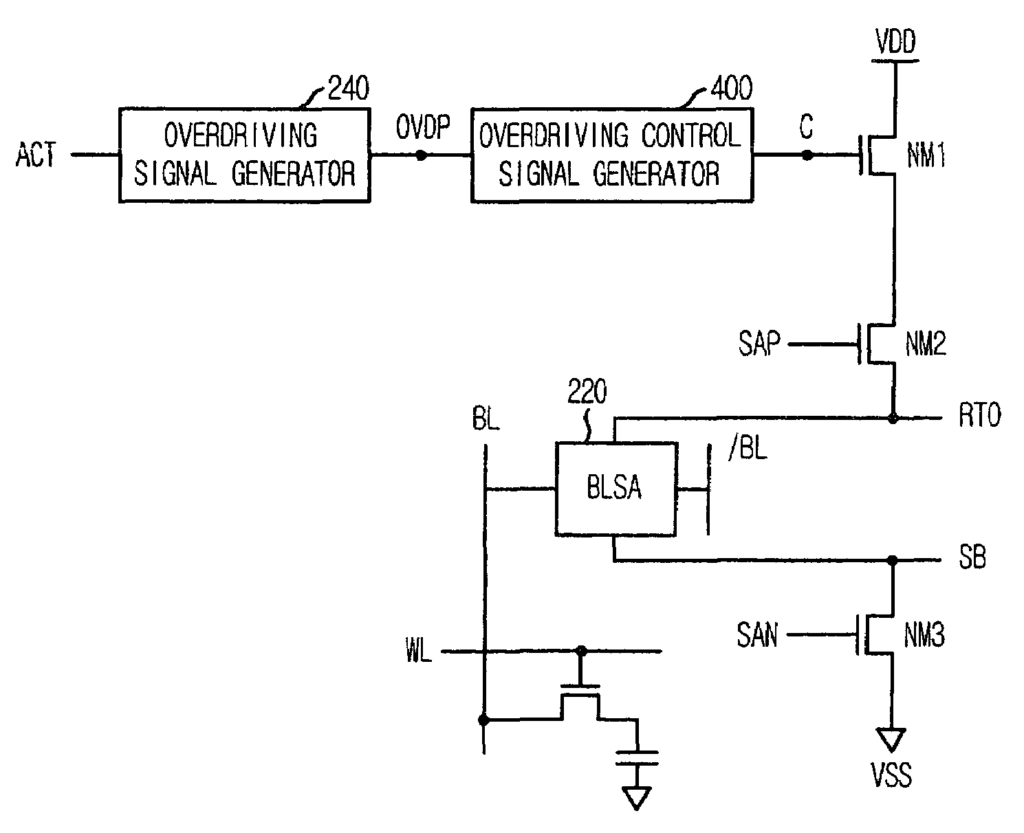
[0029]FIG. 3 is a circuit diagram of a BLSA control circuit 200 for selectively outputting an overdriving signal in accordance with the present invention.
[0030]As shown, the BLSA control circuit 200 includes a BLSA 220, an overdriving signal generator 240, a plurality of driver transistors NM1, NM2 and NM3 and an overdriving control signal generator 400.
[0031]The overdriving signal generator 240 generates an overdriving signal OVDP in response to an active command ACT. The BLSA 220 is coupled between a pull-up voltage line RT0 and a pull-down voltage line SB. The plurality of driver transistors NM1, NM2 and NM3 drives the voltage lines RT0 and SB to a specific voltage. The overdriving control signal generator 400 selectively outputs the overdriving signal OVDP according to supply voltage circumstance, i.e., whether the supply voltage is a relatively high voltage or a relatively low voltage.
[0032]Specifically, a second driver transistor NM2 drives the pull-up voltage line RT0 to a vo...
PUM
 Abstract
Description
Claims
Application Information
 - R&D
- Intellectual Property
- Life Sciences
- Materials
- Tech Scout
- Unparalleled Data Quality
- Higher Quality Content
- 60% Fewer Hallucinations
Browse by: Latest US Patents, China's latest patents, Technical Efficacy Thesaurus, Application Domain, Technology Topic, Popular Technical Reports.
© 2025 PatSnap. All rights reserved.Legal|Privacy policy|Modern Slavery Act Transparency Statement|Sitemap|About US| Contact US: help@patsnap.com


