Thermal fixing device and image forming device

a technology of fixing device and image forming device, which is applied in the field of heating devices, can solve the problems of long warm-up time, failure of fixing, and toner peeling,

Active Publication Date: 2008-09-09
COPYER
View PDF5 Cites 20 Cited by
  • Summary
  • Abstract
  • Description
  • Claims
  • Application Information

AI Technical Summary

Benefits of technology

[0027]This configuration allows the amount of heat transferred to the heater holder to be increased or decreased locally for efficiently transferring the heat of the heater to the fixing nip side. Therefore, this configuration prevents a toner-peeling problem that would develop because of an insufficient temperature when small-size paper of narrow, relatively poor fixability (such as post cards or envelops) passes through the nip.
[0030]This configuration increases the temperature of a position where an improper fixing problem, such as a toner peeling-off, is generated because of an insufficient temperature and prevents an improper fixing problem from being generated. At the same time, even if such a position, where the heat amount is large, passes no paper when a narrow recording material successively passes through the nip, the contact rate between the heater and the holder is increased in that position for the better radiation of the heat into the holder. Thus, this configuration prevents an extreme increase in the temperature of the non-paper-passage position.
[0032]More specifically, in the position where the per-unit-length heat amount is small, the thickness of the holder can be made smaller than that in the position where the heat amount is large. This configuration provides the same effect as that described above.

Problems solved by technology

However, the heat roller method has a problem that it takes a long warm-up time until the surface of the heat roller reaches a fixing temperature.
The problem with this configuration is that the rate of heat escape from the heater 1 to the heater holder 2 differs according to positions with the result that the temperature distribution in the longitudinal direction of the heater 1 is not always even during the actual use.
This results in a fixing failure due to an insufficient temperature at the ends and causes the problem of the so-called toner peeling.
In addition, the heat stress generated inside the heater 1 tends to cause a crack.
A still another problem is that, when a pressure is applied, the strength of the heater-mounting surface of the heater holder 2 is reduced to such an extent that the heater holder 2 cannot hold the heater.

Method used


Image

  • Thermal fixing device and image forming device
  • Thermal fixing device and image forming device
  • Thermal fixing device and image forming device

Examples


first embodiment

[0054]First, FIG. 9 shows the general configuration of a temperature controller of a heater in a heat fixing device used in an image forming device in this embodiment. This configuration is the same as that of a conventional device. That is, the output of a temperature sensing element (thermistor in this embodiment) 1d, provided on a heater 1, is A / D converted by an A / D converter 12 and the converted result is sent to a CPU 10. Based on the received information, the CPU 10 controls the phase and the waveform of the AC voltage to be supplied to the heater 1 via a triac 11 to control the conducting power supplied to the heater. This configuration is the same as that of other embodiments that will be described below.

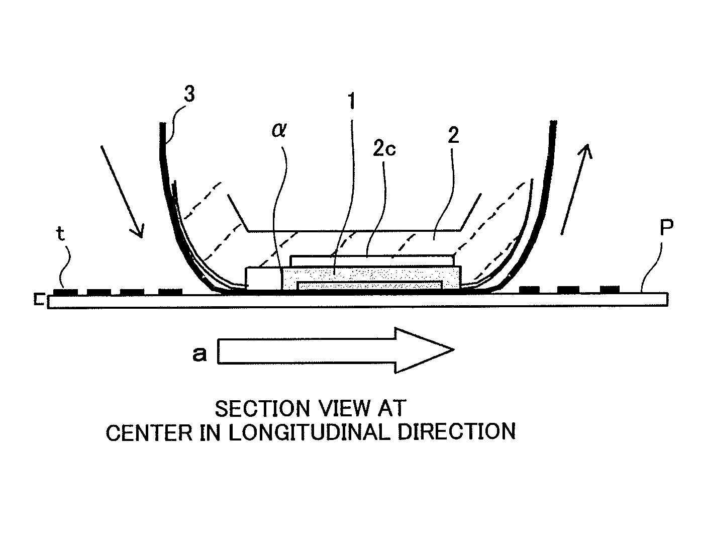
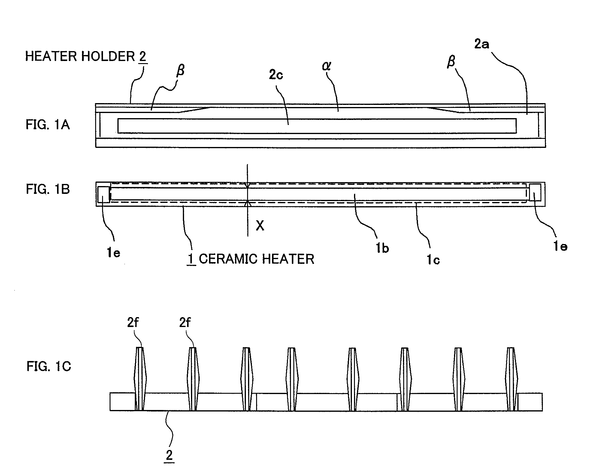
[0055]FIG. 1B is a top view of the heater 1 in the first embodiment of the present invention that has a heating element that generates heat when conducted. FIG. 1A is a top view of a heater fitting groove of a heater holder 2. FIG. 1C is a front view of the heater holder 2....

second embodiment

[0060]Next, a second embodiment of the present invention will be described. FIGS. 10A-10C are the diagrams, corresponding to those in FIG. 1, showing the second embodiment. A heater 1 is same as the heater 1 in the first embodiment described above and therefore its description is omitted. Although 1.0 mm thick in this embodiment, the heater substrate is not limited to this thickness.

[0061]In the first embodiment, the contact rate between the heater holder 2 and the heater 1 is changed. In the second embodiment, the abutment surface between a heater holder 2 and the heater 1 is uniform in shape in both the longitudinal direction and the width direction of the heater 1 as shown in FIG. 10A. That is, the contact area between the heater holder 2 and the heater 1 is uniform in the longitudinal direction. However, as shown in FIG. 10B and FIGS. 11A and 11B that are cross sections perpendicular to the longitudinal direction of the heater holder 2, the cross sectional shape of the heater ho...

third embodiment

[0063]The general configuration of the temperature controller of a heater in a heat fixing device used in an image forming device in this embodiment is the same as that in the first and second embodiments shown in FIG. 9.

[0064]FIG. 12B is a top view of a heater 1 having a heating element, which is heated through conduction, in a third embodiment of the present invention. FIG. 12A is a top view of the heater fitting groove in a heater holder 2. FIG. 12C is a front view of the heater holder 2. The structure of the other components of the heat fixing deivce is the same as that of the corresponding components of the conventional technology shown in FIGS. 6A to 6C. Although 1.0 mm thick in this embodiment, the heater substrate is not limited to this thickness.

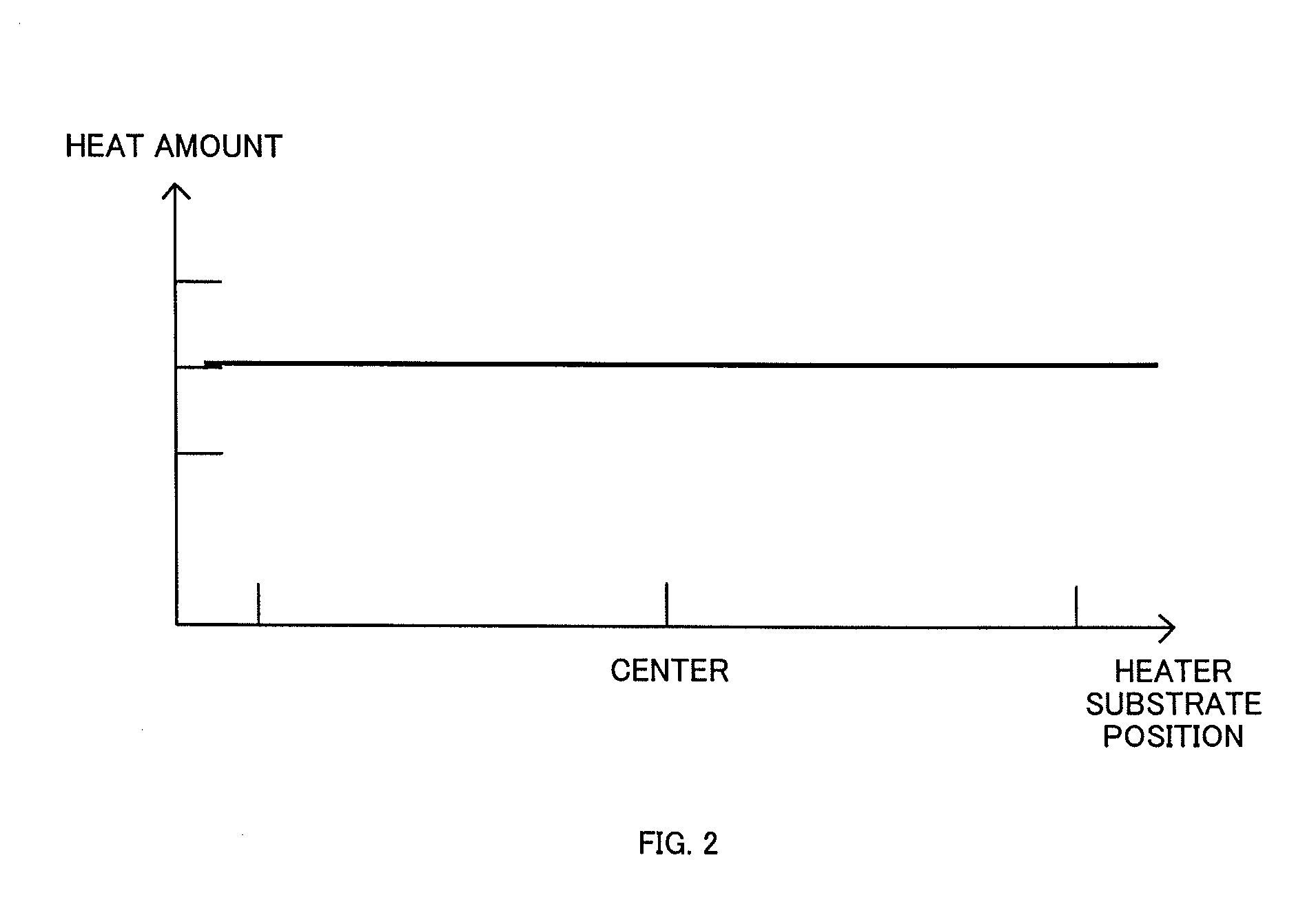
[0065]The temperature distribution of the heater 1 is even in the longitudinal direction in the first and second embodiments, while the distribution is uneven in this embodiment. That is, the heat amount at both ends of the heater 1...


PUM


Abstract

The contact rate between a heater 1 and a heater holder 2 is made higher at both ends in the longitudinal direction of the heater than at the center. Alternatively, the per-unit-length volume of the heater holder 2 in the longitudinal direction is made larger at the both ends in the longitudinal direction of the heater. In this configuration, the heat generated by the heater can easily escape into the heater holder side at the both ends but cannot easily escape into the heater holder side at the center. Although the per-unit-length heat amount in the longitudinal direction of the heater may be even, it is also possible to set the heat amount distribution in such a way that the heat amount at the both ends is larger than that at the center. The present invention prevents an improper fixing problem generated by an insufficient temperature at a particular position of a recording material and, at the same time, prevents an increase in the temperature of the non-paper-passage part that occurs when a narrow recording material is used.

Description

FIELD OF THE INVENTION[0001]The present invention relates to a heater for heating an object to be heated, and more particularly to a heat fixing device and an image forming device for melting and fixing a toner image onto a recording material (copy material) in a xerography device.RELATED ART[0002]Some of image recording devices, such as a printer, a copier, a recording device, and a facsimile, use a heat fixing device. This heat fixing device is a device, used in a recording unit of xerography, for forming an unfixed image, corresponding to image information to be recorded, on a recording material and for heat fixing the unfixed image thereon. A typical heat fixing method is a heat roller method in which a recording material is heated while it is held between, and transported, by a heat roller heated at a predetermined temperature and a pressure roller with an elastic layer thereon that presses against the heat roller. However, the heat roller method has a problem that it takes a l...

Claims


Application Information

Patent Timeline
Patent Type & Authority Patents(United States)
IPC IPC(8): G03G15/20
CPCG03G15/2042G03G15/2053
Inventor NISHIYAMA, RYUJIKAWAI, SHINTARO
Owner COPYER
Why Eureka
Try Eureka