Interlocking curtain wall insulation system

a curtain wall and interlocking technology, applied in the field of curtain wall insulation system, can solve the problems of failure to provide the means to interconnect the trough and the curtain wall on the outside edge of the trough, fire retardance and suppression, etc., and achieve the effect of maintaining the structural integrity of the system

Active Publication Date: 2008-09-16
THERMAFIBER
View PDF26 Cites 62 Cited by
  • Summary
  • Abstract
  • Description
  • Claims
  • Application Information

AI Technical Summary

Benefits of technology

[0015]Yet another object of the present invention is to provide interlocking insulation which inhibits fire damage and heat exposure in order to maintain structural integrity of the system.
[0016]According to the present invention, an interlocking curtain wall insulation system is provided. The interlocking curtain wall insulation system comprises a frame connected to a building structure having at least first and second parallel transoms, at least first and second parallel mullions, the at least first and second parallel transoms operably engaging the at least first and second parallel mullions. The device further comprises an insulation having a safing insulation extending between a floor slab and the backer bar and compressively fit therein, an upper curtain wall insulation depending from an upper insulation hanger and compressing the safing insulation, and a lower curtain wall insulation depending from a lower insulation hanger. Mullion covers may be installed adjacent the upper and lower curtain wall insulations in order to protect the mullions from exposure to flame and hot gases.

Problems solved by technology

However, providing such a perimeter void presents problems in fire retardance and suppression.
More problematic is the spread of flames and hot gases from one floor to another through the perimeter voids which consequently allow fire to spread throughout a building.
However this design fails to provide means to interconnect the trough and curtain wall on the outside edge of the trough.
However, since the curtain wall structure is typically held in place by aluminum, during fire conditions, the aluminum structure can weaken or melt allowing the curtain wall to move slightly and further allowing the safing insulation to fall from its position between the floor slab and curtain wall.

Method used


Image

  • Interlocking curtain wall insulation system
  • Interlocking curtain wall insulation system
  • Interlocking curtain wall insulation system

Examples


Embodiment Construction

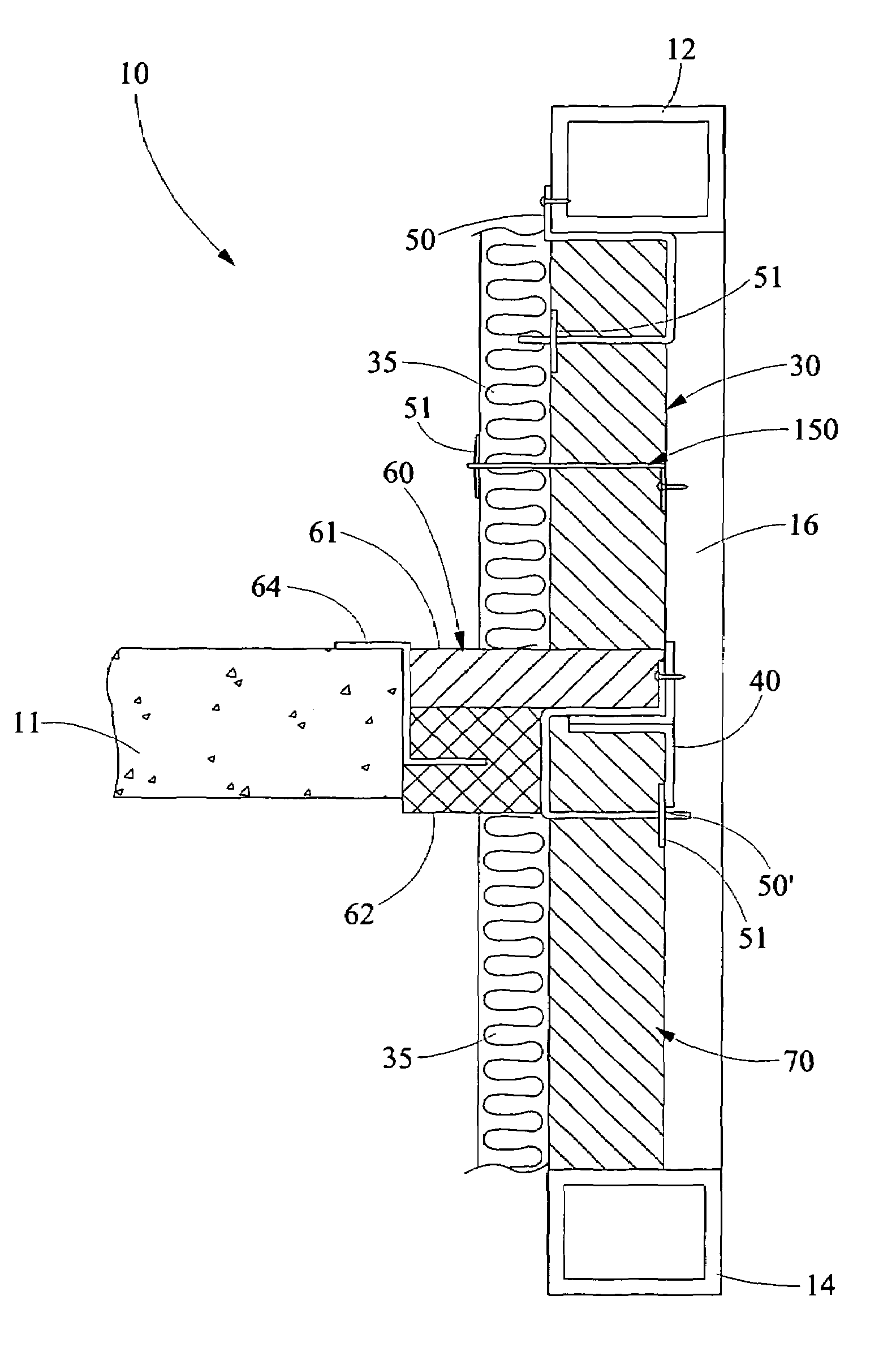
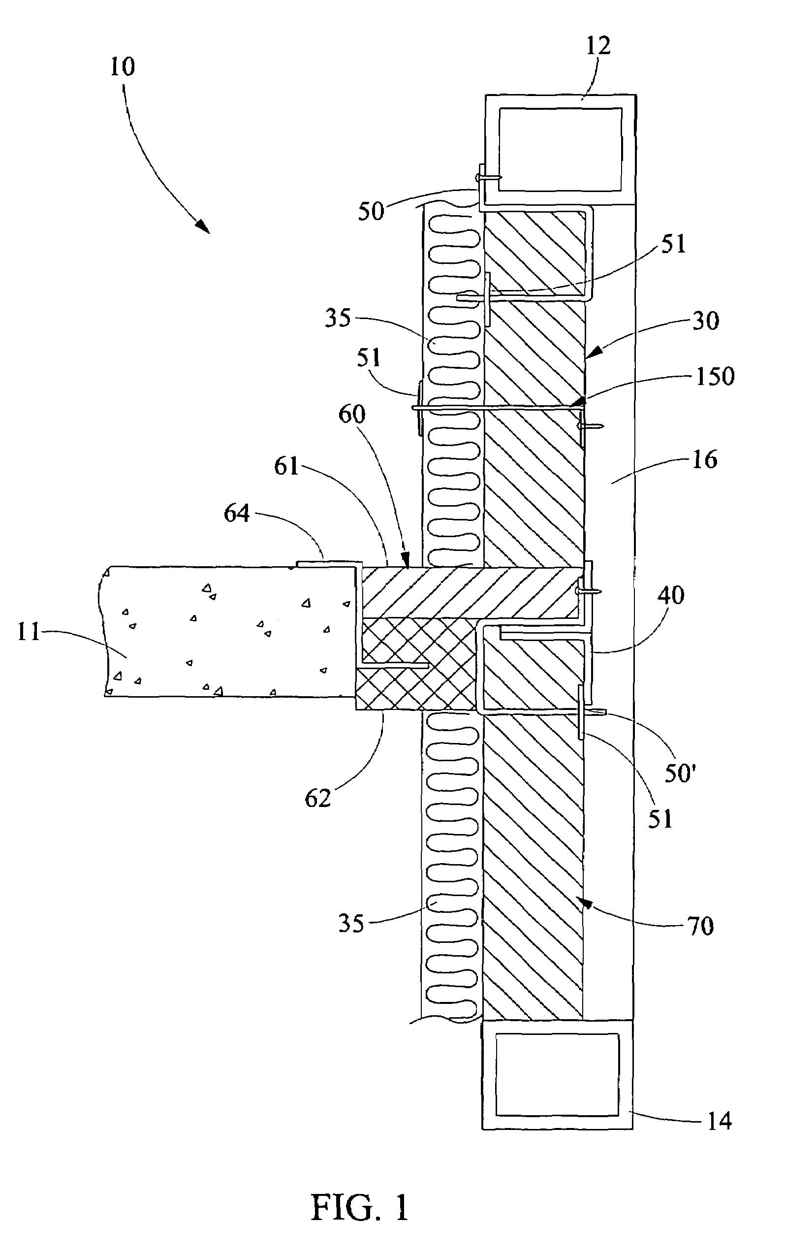
[0025]Referring now in detail to the drawings, wherein like numerals indicate like elements throughout the several views, there is shown in FIGS. 1 through 8 various aspects of an interlocking curtain wall system. The system includes a curtain wall structure, curtain wall insulation, and safing insulation arranged in compression to interlock with each other thus inhibiting the spread of flame and hot gases through adjacent floors of a high rise building. More specifically flame and hot gases are inhibited from spreading through perimeter voids between the curtain wall and the perimeter of a floor slab in a building structure.

[0026]Referring initially to FIG. 1, a side sectional view of an interlocking curtain wall system 10 of the present invention is depicted. As shown therein, the interlocking curtain wall system 10 provides an upper horizontally extending transom 12 and a lower horizontally extending transom 14 which are depicted as extending into the page. The transoms 12,14 are...


PUM


Abstract

The interlocking curtain wall insulation system comprises a frame connected to a building structure having at least first and second parallel transoms, at least first and second parallel mullions, the at least first and second parallel transoms operably engaging the at least first and second parallel mullions. The device further comprises an insulation including a safing insulation extending between a floor slab and the backer bar and compressively fit therein, an upper curtain wall insulation depending from an upper insulation hanger and compressing the safing insulation, and a lower curtain wall insulation depending from a lower insulation hanger.

Description

CROSS REFERENCES TO RELATED APPLICATIONS[0001]None.STATEMENT REGARDING FEDERALLY SPONSORED RESEARCH OR DEVELOPMENT[0002]None.REFERENCE TO SEQUENTIAL LISTING, ETC[0003]None.BACKGROUND[0004]1. Field of the Invention[0005]The present invention relates to a curtain wall insulation system which insulates adjacent floors. More specifically, the present invention relates to an interlocking curtain wall insulation which inhibits spread of fire from one floor to an upper adjacent floor through perimeter voids between an edge of a floor slab and the exterior building structure.[0006]2. Description of the Related Art[0007]Building structures utilize constructions combining steel, to provide a skeletal structure for the building, and concrete to provide floor structure. Accordingly, concrete is poured, or positioned in preformed slabs, from one side of the building to an opposed side. At interfaces between the concrete floor and exterior walls of the building, the perimeter voids are provided s...

Claims


Application Information

Patent Timeline
Patent Type & Authority Patents(United States)
IPC IPC(8): E04H1/00
CPCE04B2/88
Inventor SHRIVER, JAMES C.
Owner THERMAFIBER
Why Eureka
Try Eureka