Cable tensiometer for aircraft

Inactive Publication Date: 2008-09-16
UNITED STATES OF AMERICA AS REPRESENTED BY THE DIRECTOR OF THE NAT AERONAUTICS & SPACE ADEMINISTATION
View PDF6 Cites 22 Cited by
  • Summary
  • Abstract
  • Description
  • Claims
  • Application Information

AI Technical Summary

Benefits of technology

[0012]It is a further object of this invention to provide a cable tensiometer that positively captures and secures the cable being tested.
[0013]It is

Problems solved by technology

Currently available cable tension monitoring devices cannot be employed for this purpose.
Such tensiometers cannot be employed for measuring tension on cables that are fixed at both ends, such as those used on aircraft.
Other tensiometers have been developed to work on such fixed cables, but have other inherent problems that would obviate their use on aircraft cables.
However, this cable tensiometer employs a load cell to measure cable tension, which would be too large and heavy for operatio

Method used


Image

  • Cable tensiometer for aircraft
  • Cable tensiometer for aircraft
  • Cable tensiometer for aircraft

Examples


Example

[0019]The present invention has been designed to provide a real-time tension measuring device for in-fight use on aircraft cables. For aircraft being currently: developed, tension measurements must be precise to within 2 percent full scale (“FS”) and repeatable within 0.5 percent FS. The device must also be light-weight in order to minimize cable / control surface coupling and must also meet low-end flight environmental testing requirements.

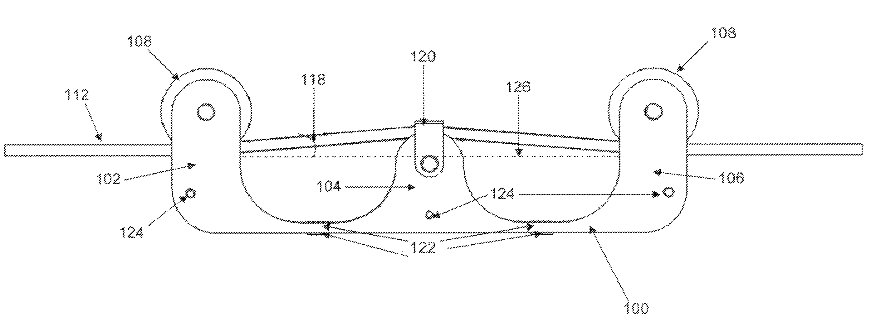
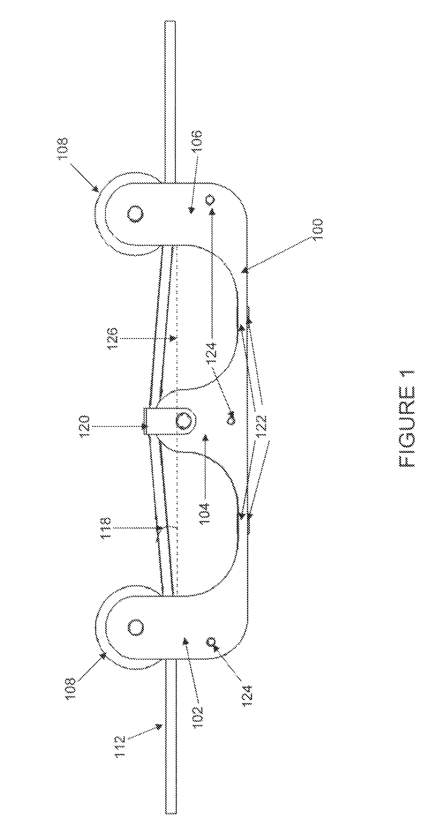
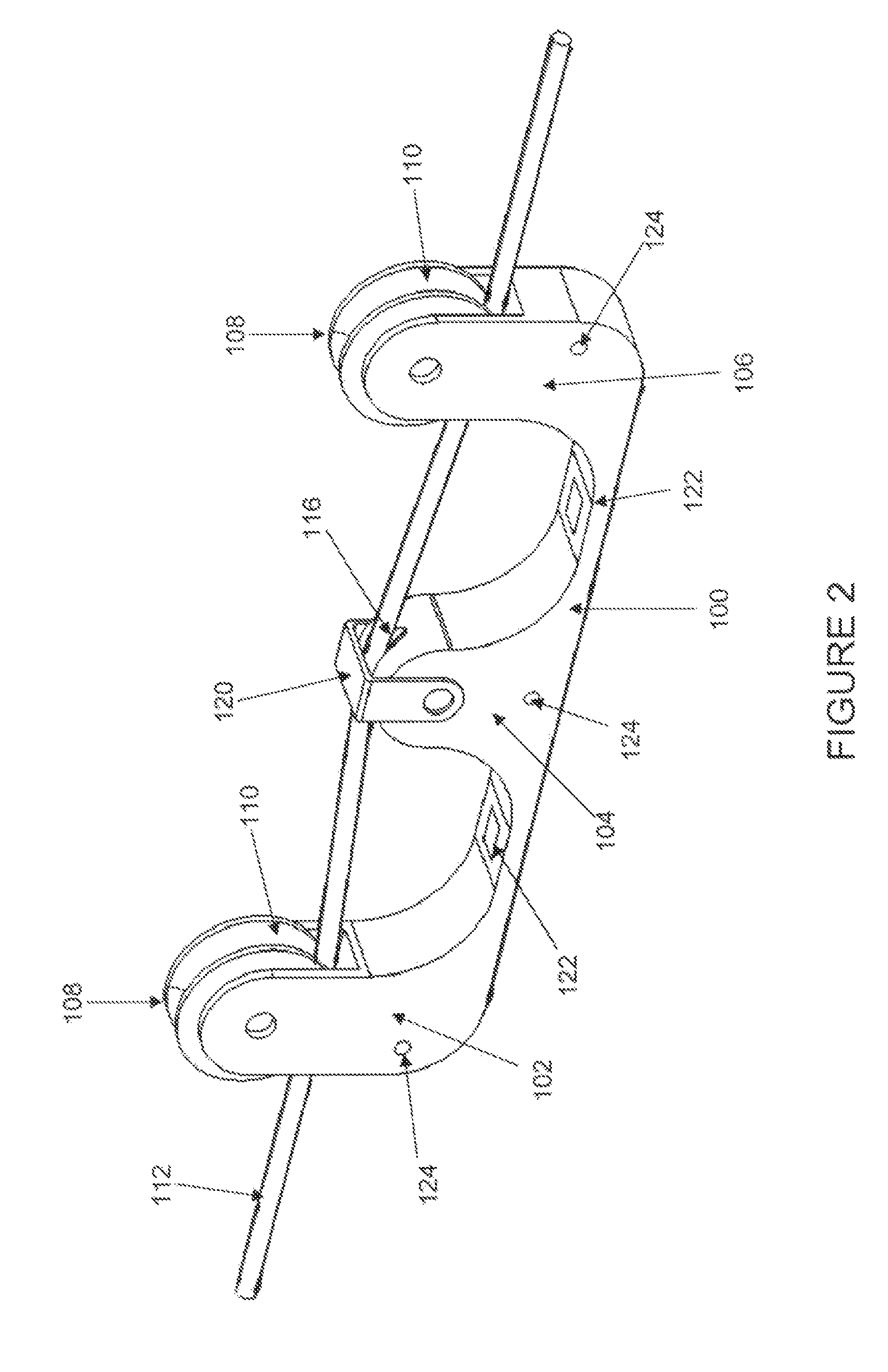
[0020]In order to meet these requirements, the invention is designed as a dual bending beam tensiometer that employs pulleys to minimize cable friction and uses the physical design to create the cable angle, rather than spacer blocks or similar extraneous components, in order to reduce the device weight.

[0021]In general, the invention is a cable tensiometer comprising a beam structure with three extensions extending from the beam structure. The middle extension is equidistant from the outer extensions and is located in the center of the beam struct...


PUM


Abstract

The invention is a cable tensiometer that can be used on aircraft for real-time, in-flight cable tension measurements. The invention can be used on any aircraft cables with high precision. The invention is extremely light-weight, hangs on the cable being tested and uses a dual bending beam design with a high mill-volt output to determine tension.

Description

STATEMENT OF GOVERNMENT INTEREST[0001]The invention described herein may be manufactured and used by or for the Government of the United States of America for governmental purposes without payment of any royalties thereon or therefor.BACKGROUND OF THE INVENTION[0002]1. Field of the Invention[0003]The present invention relates generally to measuring the tension on cables, more particularly to measuring the tension of fixed cables, and most particularly to measuring the tension of fixed cables on aircraft.[0004]2. Description of the Related Art[0005]Many aircraft employ numerous cables to make very sensitive flight related adjustments to operate the aircraft, such as to control surfaces, etc. Precise measurement of cable tension loads in real-time to ensure accurate aircraft operation related to such cables can significantly increase the effectiveness of such cables. Currently available cable tension monitoring devices cannot be employed for this purpose.[0006]Devices for measuring th...

Claims


Application Information

Patent Timeline
IPC IPC(8): G01L1/04
CPCG01L5/107G01L5/102
Inventor NUNNELEE, MARK
Owner UNITED STATES OF AMERICA AS REPRESENTED BY THE DIRECTOR OF THE NAT AERONAUTICS & SPACE ADEMINISTATION
Why Eureka
Try Eureka