Method of making customized orthodontic brackets

a technology of custom brackets and bracket slots, which is applied in the field of custom bracket making, can solve the problems that the manufacturing methods of mass production of customized brackets may not be compatible with such precision and quality requirements, and the available sufficiently precise and high quality manufacturing methods may not meet or fully satisfy the requirements of mass production at minimized costs, so as to minimize the effort of making, minimize the cost, and maximize the precision of the archwire slot of the bracket

Active Publication Date: 2018-09-04
3M INNOVATIVE PROPERTIES CO
View PDF11 Cites 0 Cited by
  • Summary
  • Abstract
  • Description
  • Claims
  • Application Information

AI Technical Summary

Benefits of technology

[0013]The invention provides advantages in the manufacturing of customized orthodontic brackets. In particular the invention helps minimizing efforts in the making of the brackets and also specifically helps maximizing the precision of the archwire slot of the bracket. The invention allows for example building up the brackets using a rapid prototyping technique at minimized costs, sufficient overall precision and using a relatively inexpensive material (for example steel), and nevertheless allows providing the bracket with an archwire slot having a maximized precision. It has been found that the precision of the archwire slot is important for a successful and rapid orthodontic treatment. In particular a customized bracket system using a rectangular archwire, allowing not only a movement by lateral forces but also a rotation of teeth by torque, the brackets should be dimensioned so that there is neither too much play between the archwire and the archwire slots nor should the archwire sit overly tight in the archwire slots. The invention helps providing brackets which meet such requirements and further help achieving minimized costs in manufacturing.

Problems solved by technology

On the other hand available manufacturing methods for mass production of customized brackets may not be compatible with such precision and quality requirements, whereas available sufficiently precise and high quality manufacturing methods may not satisfy or fully satisfy requirements for mass production at minimized costs.

Method used


Image

  • Method of making customized orthodontic brackets
  • Method of making customized orthodontic brackets
  • Method of making customized orthodontic brackets

Examples


Embodiment Construction

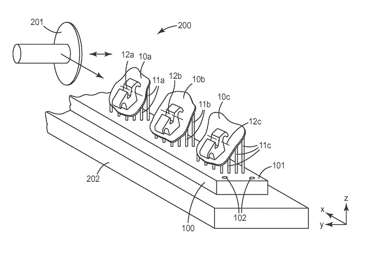
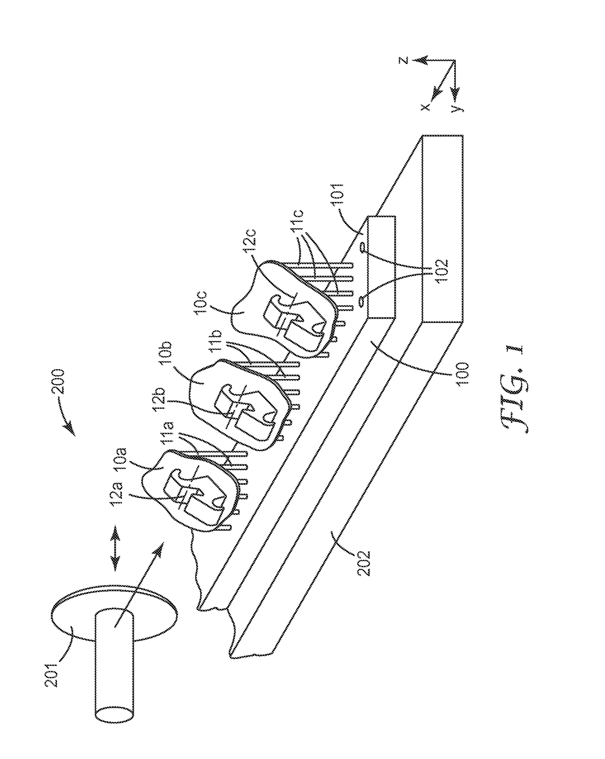
[0056]FIG. 1 shows a grinding machine 200. The grinding machine 200 has a rotatable grinding wheel 201 and a machine table 202. The grinding machine 200 is configured such that the grinding wheel 201 and the machine table 202 are linearly movable relative to each other. A similar grinding machine is also known in the field of tool making as “surface grinding machine”. However the grinding machine 200 according to the invention is equipped with grinding wheel 201, for example with an ultrathin grinding wheel. The thickness of the grinding wheel 201 is between about 0.1 mm and about 0.4 mm. Such grinding wheel preferably has a polymeric binder to prevent breaking during grinding. A suitable grinding wheel is for example available under the designation type 34 from Finzler, Schrock & Kimmel GmbH, Germany

[0057]A support plate 100 is positioned in the grinding machine 200. A plurality of bracket precursors 10a, 10b, 10c are arranged on a top surface 101 of the support plate 100. Each of ...


PUM


Abstract

A method of making customized orthodontic brackets. The method has steps of providing a plurality of customized orthodontic bracket precursors, providing one or more support structures, positioning the bracket precursors by means of the support structure(s) in a machining device and using the machining device to provide an archwire slot in each bracket precursor by material removal with the archwire slots aligned along a common path with each other. The invention helps minimizing efforts in the manufacturing and provides the brackets with a precise archwire slot.

Description

CROSS REFERENCE TO RELATED APPLICATIONS[0001]This application is a national stage filing under 35 U.S.C. 371 of PCT / US2014 / 068496, filed Dec. 4, 2014, which claims the benefit of European Application No. 13195980.1, filed Dec. 6, 2013, the disclosure of which is incorporated by reference in its / their entirety herein.FIELD OF THE INVENTION[0002]The invention relates to a method of making a customized orthodontic bracket, and in particular to a method in which a plurality of customized orthodontic bracket precursors are provided by a build-up process, and which by help of support structures provided in the build-up process are jointly provided with archwire slots by material removal. The invention further relates to a customized orthodontic bracket obtained by the method of the invention.BACKGROUND ART[0003]Orthodontic brackets are generally used in orthodontic treatments for moving one or more teeth from an initial position to a desired position in a patient's dentition. The initial ...

Claims


Application Information

Patent Timeline
Patent Type & Authority Patents(United States)
IPC IPC(8): A61C7/00B33Y50/02A61C7/14G05B15/02
CPCA61C7/002G05B15/02B33Y50/02A61C7/14A61C7/148A61C13/0004A61C13/0006A61C13/0013A61C13/0015A61C13/0018A61C13/20
Inventor PAEHL, RALF M.SCHLIMPER, RALF
Owner 3M INNOVATIVE PROPERTIES CO
Why Eureka
Try Eureka