Eureka AIR delivers breakthrough ideas for toughest innovation challenges, trusted by R&D personnel around the world.

System and methods for determining the location dynamics of a portable computing device

a portable computing and location dynamic technology, applied in direction finders using radio waves, navigation instruments, instruments, etc., can solve problems such as difficulty in obtaining, and achieve the effects of facilitating optimization of communications, reducing calibration effort, and facilitating tracking of individuals

Inactive Publication Date: 2005-12-08
MICROSOFT TECH LICENSING LLC
View PDF50 Cites 66 Cited by
  • Summary
  • Abstract
  • Description
  • Claims
  • Application Information

AI Technical Summary

Benefits of technology

[0013] The present invention disclosed and claimed herein, in one aspect thereof, comprises architecture for determining the state of motion and location of a portable computing device by analyzing the strengths of wireless signals in a wireless network. Having information about moving versus not moving and more accurate location information is useful for a variety of applications, including for systems that make decisions about the best time and device for alerting a user. The invention facilitates tracking of individuals and / or components, as well as providing relevant information (e.g., based on state, as well as inferred future state) to a user in a wireless network. The invention also facilitates optimizing communications, e.g., maintaining communications and data throughput.
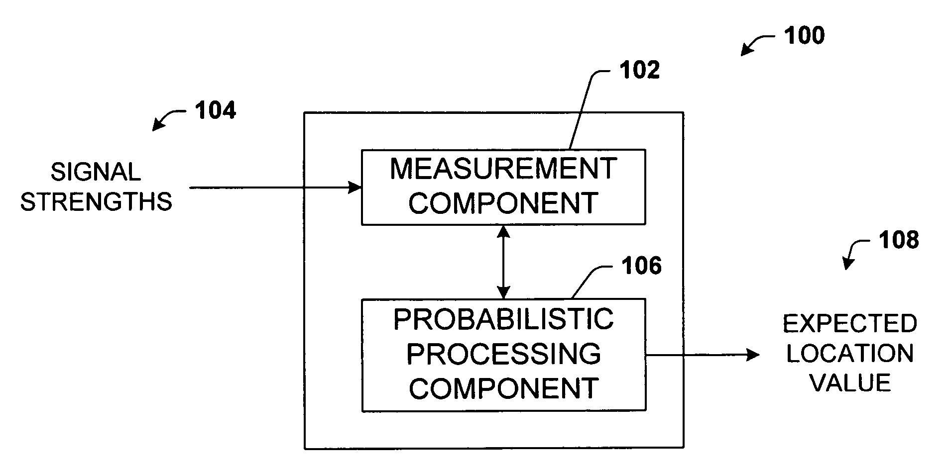
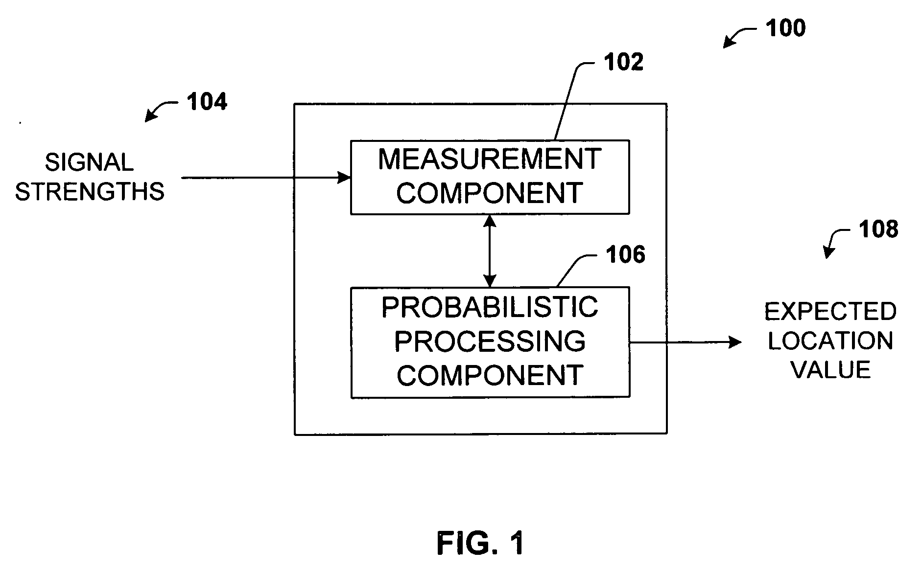
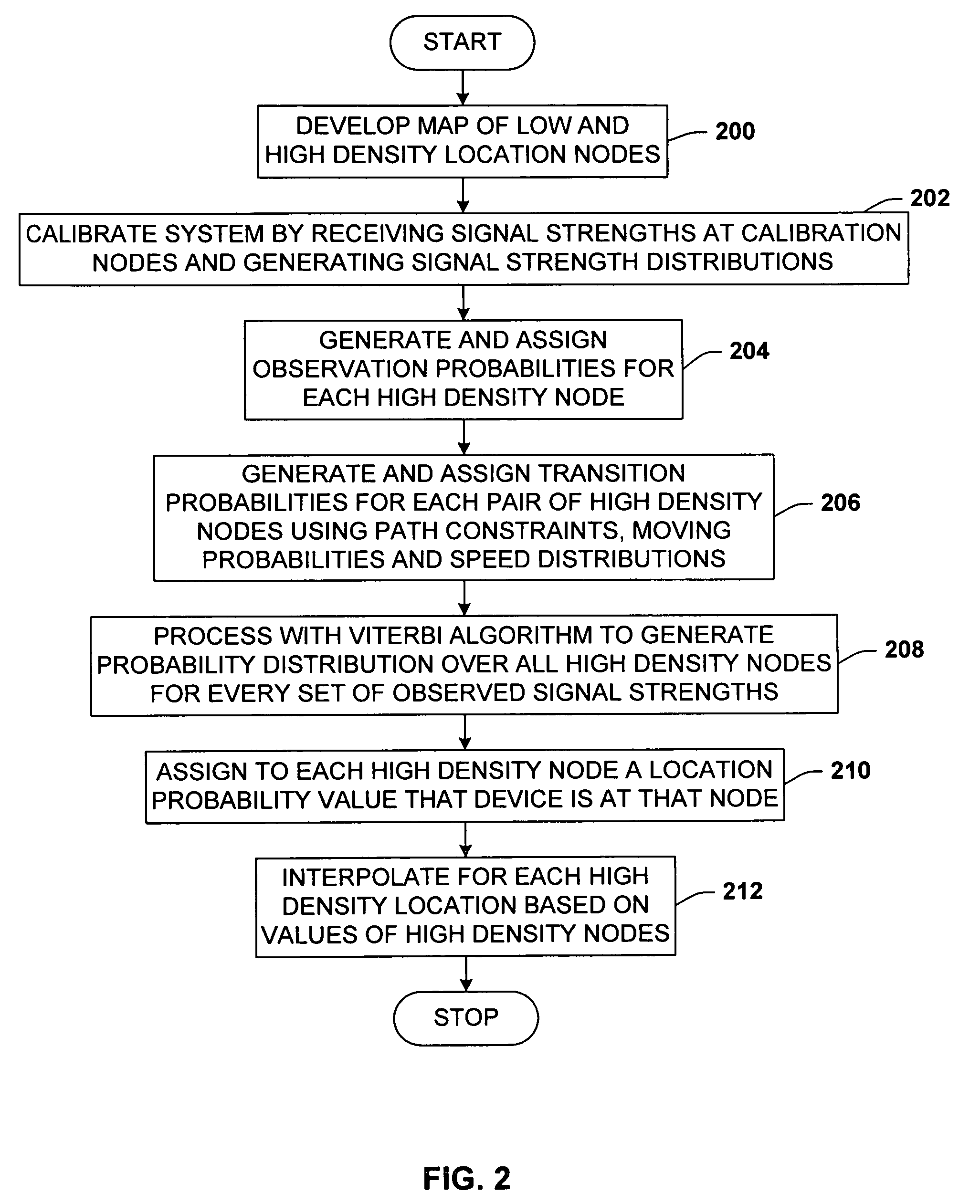
[0014] More specifically, the present invention introduces a coherent probabilistic interpretation of signal strengths and visible access points, and employs an HMM representation. However, the present invention is distinct in its use of more sophisticated models than conventional systems for providing estimates of state transition probabilities, which leads to reduced calibration effort. The novel system works from a connected graph of discrete (x, y) high-density location nodes on the floor of the building. Upon the receipt of a set of signal strengths, the HMM is used to compute the probability that the device is at each of the location nodes. At each point in time, each pair of location nodes has a transition probability associated therewith that gives the probability that the device will move from the first member of the pair to the second. These transition probabilities are a function of elapsed time since the last signal strength reading, the distance between the pair of nodes, and the probability that the device is currently in motion. Rather than considering the distance between a pair of nodes to be the Euclidian distance, the shortest path distance is based on a constraint-sensitive path-planning algorithm that takes into consideration the walls of a building floor plan such that paths cannot pass through walls.
[0015] The invention includes probabilistic methods for enhancing robustness and reducing the training (or calibration) effort associated with location services based on ambient IEEE 802.11 infrastructures. The disclosed architecture employs a probabilistic graph where locations are nodes and transition probabilities among nodes are derived as a function of the building (or floor plan) layout, expected walking speeds of pedestrians, and an independent inference of whether or not a device is in motion. Calibration of signal strengths is relatively easy compared to other systems of this type. The present invention provides a relatively accurate location sensing system while minimizing calibration effort by including interpolation of signal strengths from a sparsely sampled set of calibration nodes, exploiting path constraints imposed by the building's interior structure (e.g., walls and doors), integrating the consideration of human pedestrian speeds, making independent inferences about whether or not a client device is in motion, and folding in these inferences into the location analysis. Thus the mobile client is as smart as possible in order to maintain accuracy in spite of sparse calibration data, which can be tedious to obtain. Overall, the present invention provides a principled framework representing a superior tradeoff between accuracy and calibration effort by including path, time, and rate constraints that are important for extracting valuable data out of the typically noisy raw signal data.
[0016] The disclosed system facilitates visiting a much sparser set of location nodes for calibration then conventional systems. Interpolation is employed to estimate observation probabilities at the high-density location nodes from the lower density calibration nodes. This significantly reduces the necessary calibration effort. The graph of location nodes, transition probabilities, and observation probabilities are combined with a Viterbi algorithm to compute a probability distribution over the high-density nodes from every set of observed signal strengths obtained during live operation of the system. The expected value of device location is reported as an ultimate result, showing that the median error is approximately 1.53 meters.

Problems solved by technology

Thus the mobile client is as smart as possible in order to maintain accuracy in spite of sparse calibration data, which can be tedious to obtain.

Method used


Image

  • System and methods for determining the location dynamics of a portable computing device
  • System and methods for determining the location dynamics of a portable computing device
  • System and methods for determining the location dynamics of a portable computing device

Examples


Embodiment Construction

[0033] The present invention is now described with reference to the drawings, wherein like reference numerals are used to refer to like elements throughout. In the following description, for purposes of explanation, numerous specific details are set forth in order to provide a thorough understanding of the present invention. It may be evident, however, that the present invention may be practiced without these specific details. In other instances, well-known structures and devices are shown in block diagram form in order to facilitate describing the present invention.

[0034] As used in this application, the terms “component” and “system” are intended to refer to a computer-related entity, either hardware, a combination of hardware and software, software, or software in execution. For example, a component may be, but is not limited to being, a process running on a processor, a processor, an object, an executable, a thread of execution, a program, and / or a computer. By way of illustrat...


PUM


Abstract

A location system for locating and determining the motion and velocity of a wireless device. The methods include direct inferences about whether a device is in motion versus static based on a statistical analysis of the variation of radio signal strengths over time. The system is trained according to a sparse set of identified locations from which signal strengths are measured. The system uses the signal properties of the identified locations to interpolate for a new location of the wireless device. The system uses a probabilistic graph where the identified locations of the floor plan, expected walking speeds of pedestrians, and independent inference of whether or not the device is in motion are used to determine the new location of the device.

Description

CROSS-REFERENCE TO RELATED APPLICATIONS [0001] This application is a divisional of U.S. patent application Ser. No. 10 / 610,190, entitled “SYSTEM AND METHODS FOR DETERMINING THE LOCATION DYNAMICS OF A PORTABLE COMPUTING DEVICE”, filed Jun. 30, 2003, which is related to pending U.S. patent application Ser. No. 10 / 423,093 entitled “CALIBRATION OF A DEVICE LOCATION MEASUREMENT SYSTEM THAT UTILIZES WIRELESS SIGNAL STRENGTHS”, filed Apr. 25, 2003. This application is also related to co-filed, copending applications MS303523.08 / MSFTP456USB and MS303523.09 / MSFTP456USC. The entireties of these applications are incorporated herein by reference.TECHNICAL FIELD [0002] This invention relates to equipment location systems, and more specifically, to a probabilistic location system that determines device location and motion using wireless signal strengths. BACKGROUND OF THE INVENTION [0003] The increasing ubiquity of wireless network access has motivated the creation of several methods aimed at ide...

Claims


Application Information

Patent Timeline
Patent Type & Authority Applications(United States)
IPC IPC(8): G01S19/48G01S5/02G01S11/06H04L29/06H04W64/00H04W84/12
CPCG01C21/206Y10S707/99937H04L29/06G01S5/0252G01S5/02524H04L9/40G01S11/06
Inventor KRUMM, JOHN C.HORVITZ, ERIC J.
Owner MICROSOFT TECH LICENSING LLC
Why Eureka
Eureka Blog
Learn More