Wrist implant apparatus and method

a wrist implant and wrist technology, applied in the field of wrist implant apparatuses and methods, can solve the problems of wrist implants that require excessive bone resection, less than satisfactory, and are more susceptible to post-operative fracture, so as to minimize future implant failure, and facilitate hand flexion and extension.

Active Publication Date: 2009-05-12
SMITH & NEPHEW INC
View PDF4 Cites 66 Cited by
  • Summary
  • Abstract
  • Description
  • Claims
  • Application Information

AI Technical Summary

Benefits of technology

[0010]The prosthetic wrist implants and methods disclosed herein combine a number of positive design features to provide optimal range of motion with acceptable flexion and extension of the hand. This is accomplished by incorporating an implant with a unique geometry matching that of the natural wrist. For example, an inclined articular surface of a radial component of the implant mimics the articular surface of a radius. In addition, a carpal component and bearing component of the wrist implant are designed to linearly engage with the use of simple tools so that the bearing component completely covers certain exposed portions of the carpal component, eliminating metal-on-metal contact between the radial component and the carpal component and minimizing future implant failure. The wrist implant empowers the surgeon the option to select the best method of implant fixation for the patient by utilizing either bone cement for cement fixation or implant interference fit for press-fit fixation. The carpal plate is primarily secured to the carpus bones by way of screws with the addition of either bone cement of press-fit fixation methods. The radial implant is secured to the distal radius bone by either bone cement of press-fit fixation methods. This, coupled with a range of implant sizes, from extra-small to large, allows the surgeon to determine and select the optimal fit with minimal bone resection. These aspects result in a stronger attachment as well as stronger bone structure post-operatively.
[0013]Accordingly, it is an object to provide improved prosthetic wrist implants and methods designed to minimize effort required to join functioning components and to also minimize wear and dislocation on implant components that can result in implant failure.

Problems solved by technology

Fusion however, proved to be less than satisfactory since it left the patient with no movement in the wrist.
Because of the size needed to achieve the necessary strength, wrist implants have typically required excessive amounts of bone to be resected.
This significantly weakened the bones making them more susceptible to post-operative fracture.
Furthermore, once fracture occurs, because of the significant loss of bone due to resection, there may not be enough bone left to permit a satisfactory fusion procedure.
This may leave a patient without any avenue of treatment, not even fusion.
Another drawback with prior prosthetic wrist implants is that they do not provide the patient with acceptable functionality.
Part of the problem is that these implants have not adequately matched the geometry of the natural wrist.
As a result, flexion and extension of the hand return to a natural position, and range of motion have all been less than optimum, and the patient is left with less functionality of the implanted wrists than with a natural wrist.
Another difficulty with prior wrist implants involves the means of attaching the implant to the radius and carpal bones.
If the attachment is not secure enough, or the implant itself is not strong enough, the stability of the attachment may not be adequate under normal use of the wrist.
However, as discussed above, this results in more resection and weakening of the bone.
As a result of the above issues, existing prosthetic wrist implants have not always achieved adequate levels of patient satisfaction and have sometimes resulted in unacceptable complication rates.
Another problem with wrist implant procedures is the unavailability of special instruments for performing the implant operations.
Tools currently available make excavation of a hole, which is cut into the bone to position the implant, difficult and imprecise.
As a result, malrotation of the tool can occur which results in misalignment of the implant.
Further, specialty guides are unavailable to assist in alignment of a cutting blade during resection of the bone into which the implant is to be fitted.
This may result in excess bone material being removed during the resection.
A final problem with prior art wrist implants is the manner in which the implant is pieced together and functions, and the potential to limit the life of the implant due to particle contamination.
This joining action requires the surgeon to use a large, cumbersome tool to grasp both the bearing member and the carpal implant and slide them together laterally for a tight fit.
Second, once the bearing member and carpal implant are joined, the metal surface of the carpal implant is exposed underneath the bearing member.
At extreme flexions of the wrist, the metal radial implant can rub against the metal exposed portion of the carpal implant, causing the shedding of metallic particulate matter.
This metal particulate matter can contaminate surrounding tissue and lead to cell degeneration and death.
Once surrounding tissue is damaged, the implant is loosened and eventually this loosening can lead to implant failure.

Method used


Image

  • Wrist implant apparatus and method
  • Wrist implant apparatus and method
  • Wrist implant apparatus and method

Examples


Embodiment Construction

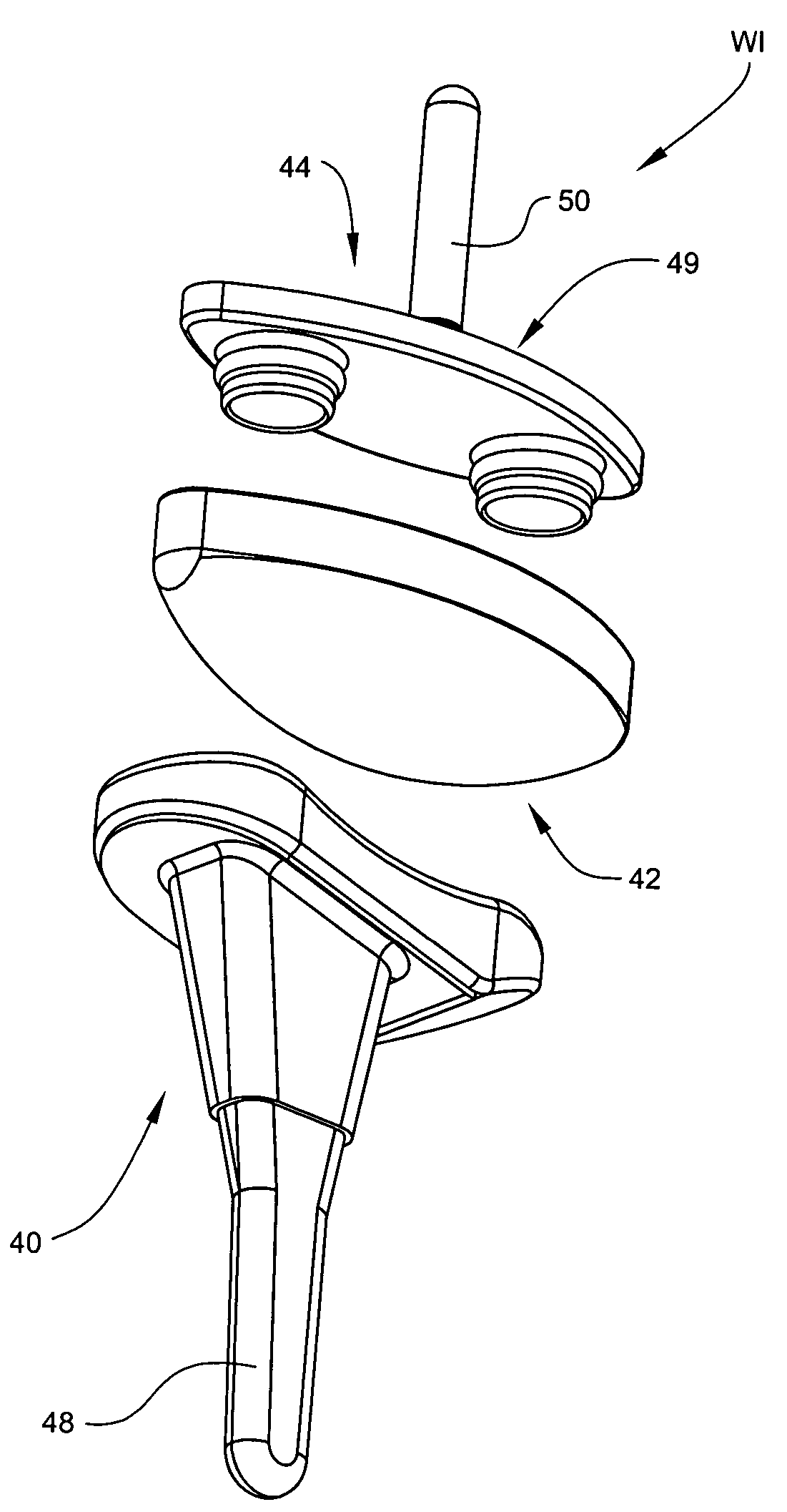
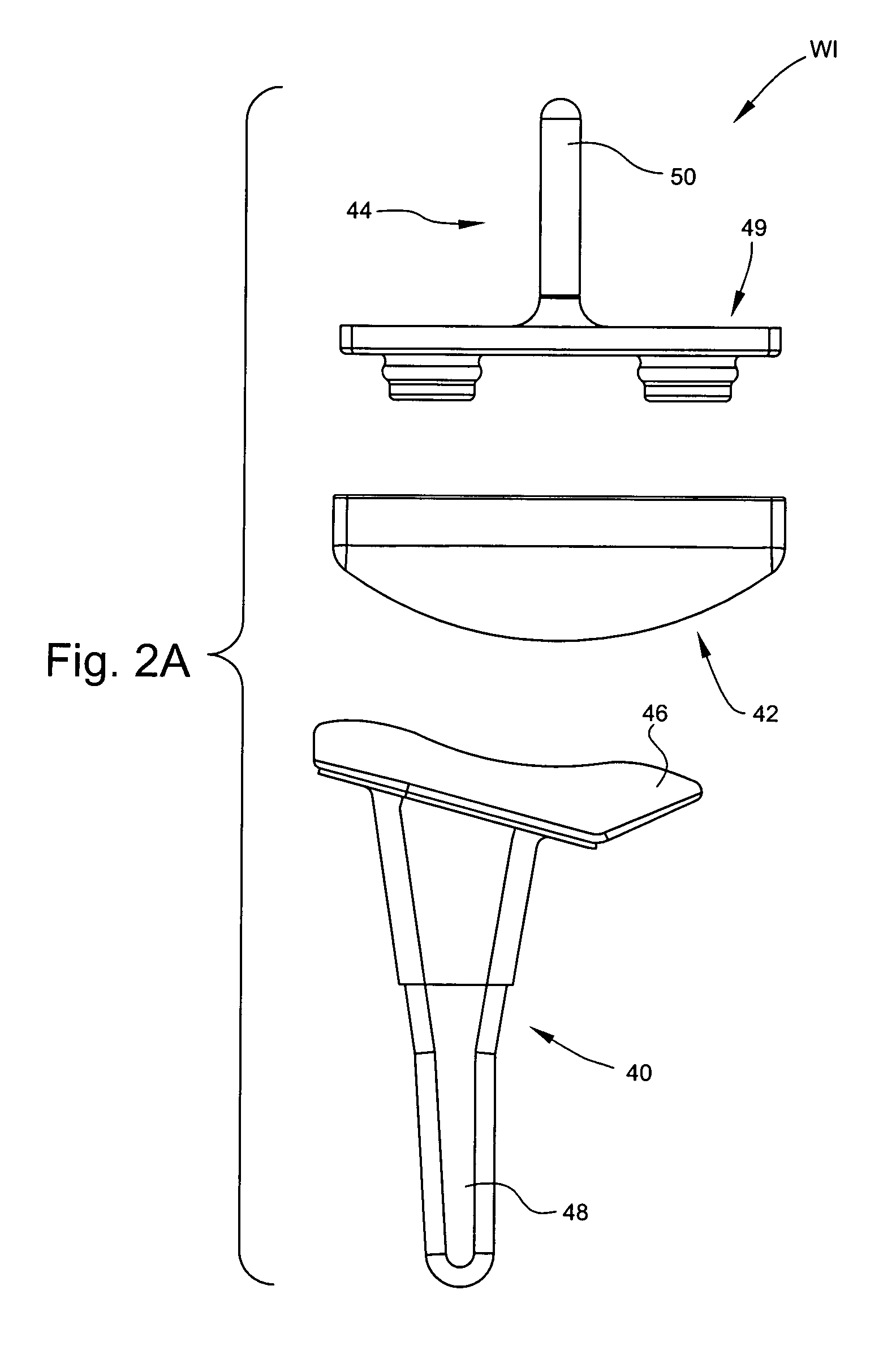
[0039]The present subject matter discloses prosthetic wrist implants and methods. The prosthetic wrist implants and methods disclosed herein minimize bone resection and allow natural articulation of the hand. An implant is utilized with a geometry that matches that of a natural wrist to afford a normal range of motion to the patient and also is designed to linearly engage and minimize future implant failure. An inclined articular surface of the radial component of each implant mimics the articulate surface of the distal radius bone. The small size and method of attachment of the implants minimize bone resection. The carpal component and bearing component are designed to linearly engage with the use of simple tools so that the bearing component can completely cover certain exposed portions of the carpal component, eliminating metal-on-metal contact between the radial component and the carpal component and minimizing future implant failure. The wrist implant may utilize screws, bone g...


PUM


Abstract

Prosthetic wrist implants and methods are provided. The prosthetic wrist implant includes a radial component including a base member having an upper bearing surface and a lower surface having an elongated radial stem for fixation to a radius bone. The elongated radial stem can be in an off-center position in relation to a center of the lower surface. A carpal component is also provided including a substantially planar base member having an upper surface and a lower surface with at least one socket protrusion extending therefrom, and may further included an elongated carpal post member for fixation to one or more carpal bones. An articulating bearing component for placement between the radial and carpal components is provided and includes an upper surface defining at least one socket recess and a lower bearing surface for cooperative engagement with the upper bearing surface of the radial component. The socket protrusion of the carpal component is adapted to linearly engage the socket recess of the bearing component to desirably limit rotational and translational movement of the carpal component relative to the bearing component.

Description

RELATED APPLICATIONS[0001]This application claims the benefit of U.S. Provisional Patent Application Ser. No. 60 / 411,824, filed Sep. 18, 2002; the disclosure of which is incorporated herein by reference in its entirety.TECHNICAL FIELD[0002]The present subject matter relates to prosthetic implants and more particularly to wrist implant apparatuses and methods utilizing a wrist implant with a geometry that closely matches that of the natural wrist, which minimizes bone resection, and which can be installed in a manner to minimize future implant failure.BACKGROUND ART[0003]The replacement of degenerated natural joints with man-made prosthetic replacements is well known, including the replacement of the wrist joint. Prior to the introduction of prosthetic joint replacement, patients with wrist diseases such as radio-carpal arthritis were often treated with a fusion procedure. Fusion typically involved an implantable joint replacement that prevented articulation of the wrist. Fusion howe...

Claims


Application Information

Patent Timeline
IPC IPC(8): A61F2/42A61B17/00A61B17/15A61B17/16A61B17/17A61FA61F2/00A61F2/30A61F2/46
CPCA61B17/15A61B17/1659A61B17/1686A61F2/4261A61B2017/0046A61F2/4606A61F2/4684A61F2002/30253A61F2002/30616A61F2002/30708A61F2002/3082A61F2002/30878A61F2002/4264A61F2002/4631A61F2230/0076A61F2250/0084A61F2310/00023A61F2310/00029A61B2017/1782A61B17/1782
Inventor REINDEL, ERIC S.
Owner SMITH & NEPHEW INC
Why Eureka
Try Eureka