Segmented pitch ring for a wind turbine blade pitch system

a technology of pitch rings and wind turbines, which is applied in the direction of motors, shafts, engine fuctions, etc., can solve the problems of ever larger diameter pitch rings that need to be casted, and achieve the effects of high stress, easy manufacturing of pitch rings, and high strength

Active Publication Date: 2020-11-03
VESTAS WIND SYST AS
View PDF18 Cites 0 Cited by
  • Summary
  • Abstract
  • Description
  • Claims
  • Application Information

AI Technical Summary

Benefits of technology

[0011]Current blade pitch rings are typically casted as a single part or piece, and it becomes problematic for blade pitch rings of ever larger diameter to be casted in this way because of the significant amount of empty space in the ring centre and because of reduced structural integrity. The present invention is advantageous in that the blade pitch ring is formed of a plurality of (smaller) segments, which are easier to manufacture, particularly for utility-scale wind turbines.
[0029]The rolling process may be a cold-rolling process. In particular, this may be performed manually to maximise the precision of the segments.

Problems solved by technology

Current blade pitch rings are typically casted as a single part or piece, and it becomes problematic for blade pitch rings of ever larger diameter to be casted in this way because of the significant amount of empty space in the ring centre and because of reduced structural integrity.

Method used


Image

  • Segmented pitch ring for a wind turbine blade pitch system
  • Segmented pitch ring for a wind turbine blade pitch system
  • Segmented pitch ring for a wind turbine blade pitch system

Examples


Embodiment Construction

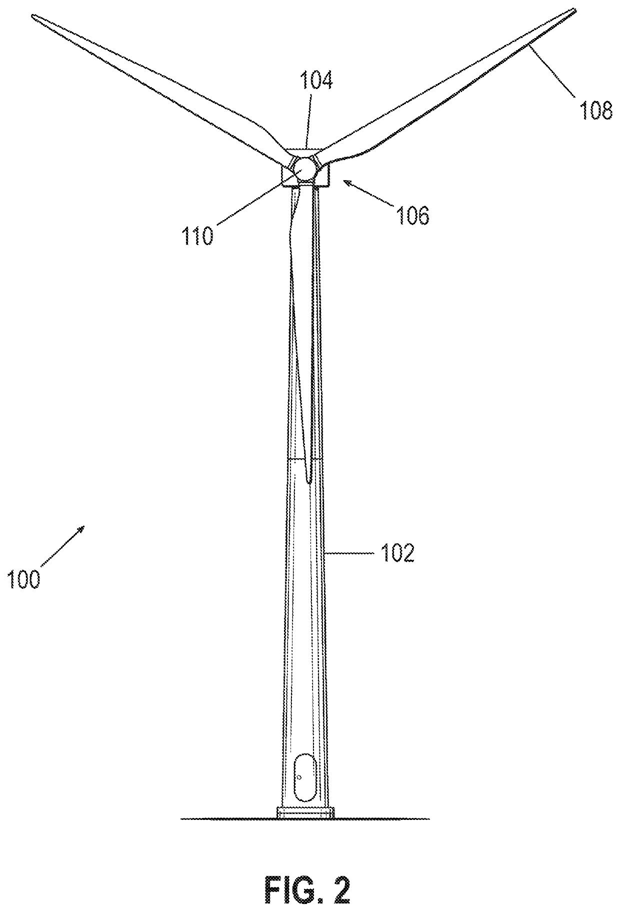
[0044]FIG. 2 is a front view of a wind turbine 100 according to the present invention. The wind turbine 100 comprises a tower 102, a nacelle 104 located at the top of the tower 102, and a rotor-hub assembly 106 mounted to the nacelle 104. The rotor-hub assembly 106 comprises three turbine blades 108 affixed to a central hub 110. The blades 108 are arranged to cause rotation of the rotor-hub assembly 106 when wind is incident on the blades 108 in a direction substantially perpendicular to and into the plane of the page. The central hub 110 is connected to a main shaft housed in the nacelle 104, which in turn is connected to a generator also in the nacelle 104. The central hub 110 causes the main shaft to turn and this rotational energy is converted into electricity by the generator.

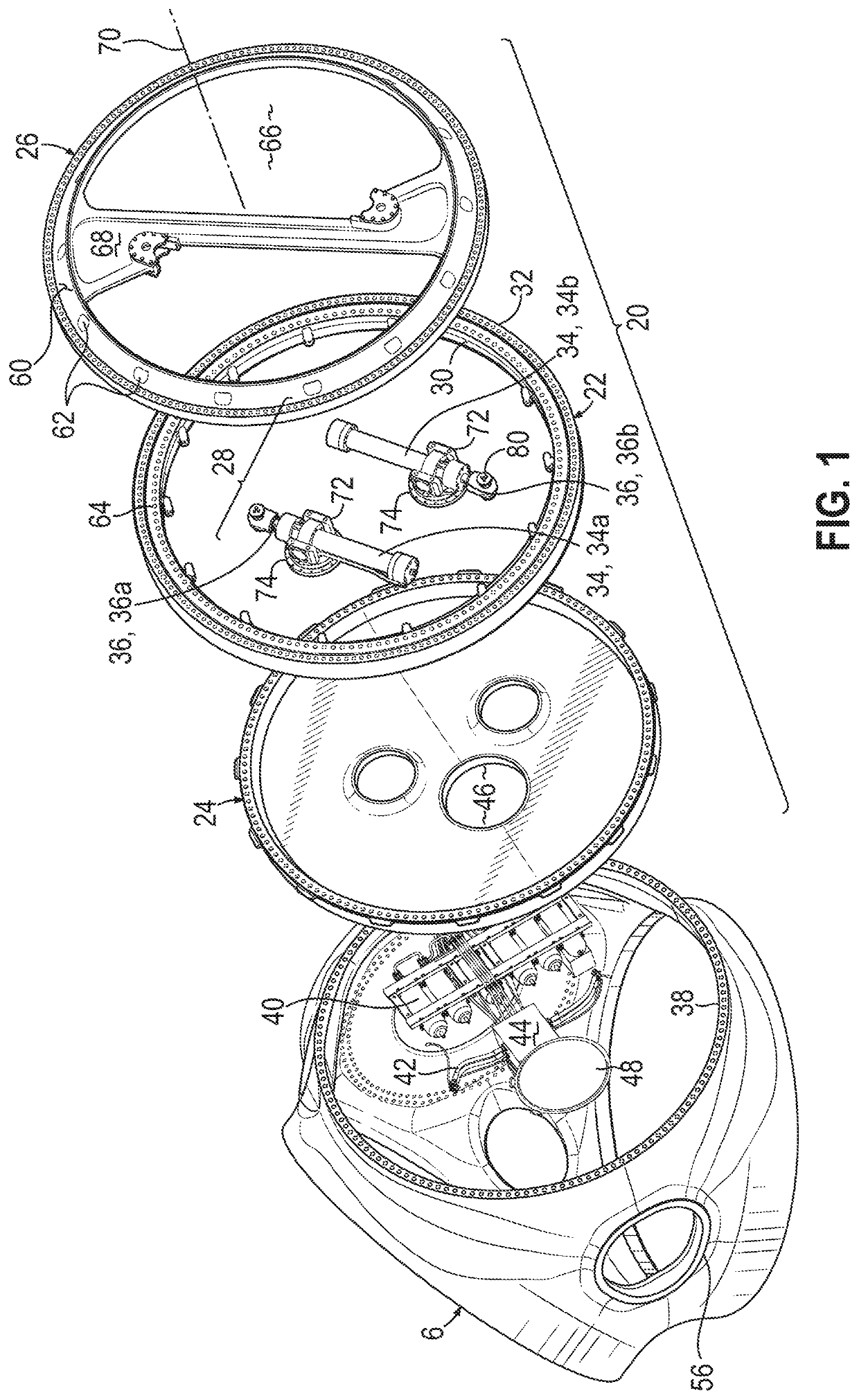
[0045]Each wind turbine blade 108 is mounted to the central hub 6 by a pitch system similar to the pitch system described by way of background with reference to FIG. 1. Accordingly, reference to FIG. 1 sho...


PUM


Abstract

The present invention provides a segmented pitch ring for use in a blade pitch system of a wind turbine. The segmented pitch ring is formed of a plurality of segments manufactured by different processes. In particular, one or more of the segments are formed by a rolling process, and one or more of the segments are formed by a casting process. The segments are arc-shaped or include arc-shaped sections that in combination define a substantially circular circumference of the pitch ring.

Description

TECHNICAL FIELD[0001]The present invention relates generally to wind turbines and more specifically to a pitch ring for use in a blade pitch system of a wind turbine. The invention also relates to a method of making a pitch ring.BACKGROUND[0002]Wind turbines typically include a rotor with large blades driven by the wind. The blades convert the kinetic energy of the wind into rotational mechanical energy. Typically, the mechanical energy is transferred via a drive train to a generator, which then converts the energy into electrical power.[0003]Most modern wind turbines control power output by pitching the blades relative to the wind. Thus, each blade is mounted to a hub by a pitch system that allows relative movement between the blade and the hub. The pitch system comprises a pitch bearing, which typically includes concentrically-arranged inner and outer bearing rings. One of the bearing rings (either the inner or the outer ring) is attached to the blade and the other is attached to ...

Claims


Application Information

Patent Timeline
Patent Type & Authority Patents(United States)
IPC IPC(8): F03D80/70F03D7/02F16C33/60F03D1/06
CPCF03D1/0658F03D7/0224F03D80/70F16C33/60F16C2360/31F05B2230/21F05B2260/79Y02E10/72F05B2230/26F05B2240/50Y02P70/50
Inventor CHRISTENSEN, MICHAELKABUS, SIMONMARKUSSEN, ERIKNEUBAUER, JESPER LYKKEGAARD
Owner VESTAS WIND SYST AS
Why Eureka
Try Eureka