
Recovering added precision from L-bit samples by dithering the samples prior to an averaging computation

a technology of l-bit samples and added precision, applied in computing, visual presentation, instruments, etc., can solve the problems of increasing the complexity and amount of data being sent to display devices, increasing the complexity of images displayed, and incorporating graphics processors with a great deal of processing power, so as to facilitate this maximization, maximize the precision length m, and maximize the precision of the gamma corrected pixel value

Inactive Publication Date: 2005-05-17
ORACLE INT CORP
View PDF7 Cites 0 Cited by
  • Summary
  • Abstract
  • Description
  • Claims
  • Application Information

AI Technical Summary

Benefits of technology

[0023]In some embodiments, the sample-to-pixel calculation unit may use the M-bit pixel value to perform gamma correction. In other words, the sample-to-pixel calculation unit may determine a gamma corrected pixel value (e.g. by table lookup) in response to the M-bit pixel value. In order to maximize the precision of the gamma corrected pixel value, the system may maximize the precision length M for any given value of storage length L. Advantageously, dithering may facilitate this maximization. In one embodiment, precision length M is at least 12 and the gamma corrected pixel value has at least 10 bits of precision.

Problems solved by technology

Modern graphics systems, however, incorporate graphics processors with a great deal of processing power.
This change has resulted in an increase in both the complexity and amount of data being sent to the display devices.
Similarly, the images displayed are now more complex and may involve advanced techniques such as anti-aliasing and texture mapping.
As a result, without considerable processing power in the graphics system, the host processor would spend a great deal of time performing graphics calculations.
This could rob the host processor of the processing power needed for performing other tasks associated with program execution, and thereby dramatically reduce the overall performance of the computer system.
These systems, however, have generally suffered from limitations imposed by the conventional frame buffer, and by the added latency caused by the render buffer and filtering hardware.
A number of adverse perceptual effects may be observed when the value NQ is not sufficiently large.
However, a larger value for NQ implies a larger and more costly pixel frame buffer.
It may be difficult for a graphics system to realize a value for NQ which is large enough to eliminate (or sufficiently reduce) the adverse perceptual effects since the associated memory costs may be high.
However, traditional attempts at dithering have typically been limited to off-line, software applications.

Method used


Image

  • Recovering added precision from L-bit samples by dithering the samples prior to an averaging computation
  • Recovering added precision from L-bit samples by dithering the samples prior to an averaging computation
  • Recovering added precision from L-bit samples by dithering the samples prior to an averaging computation

Examples


second embodiment

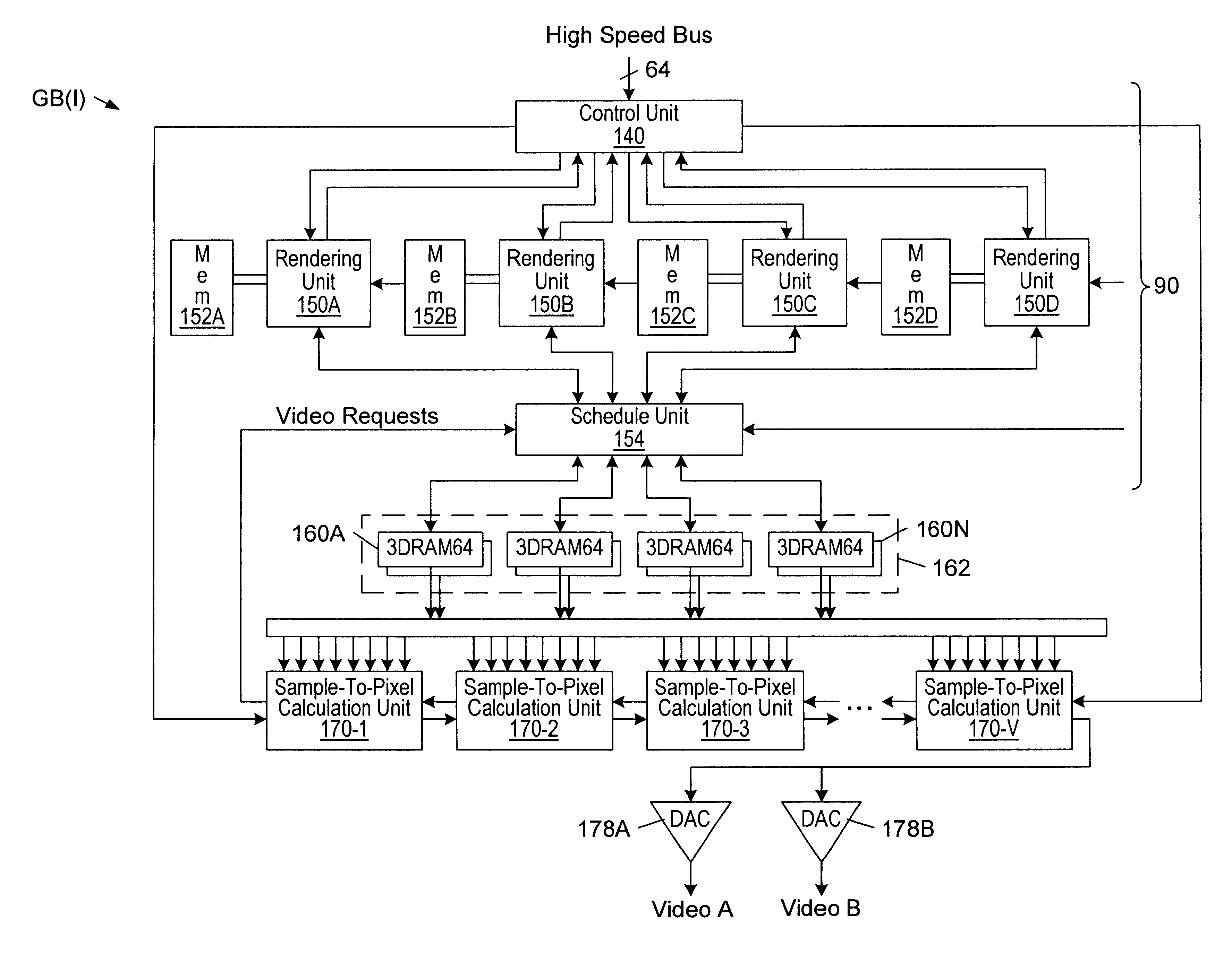
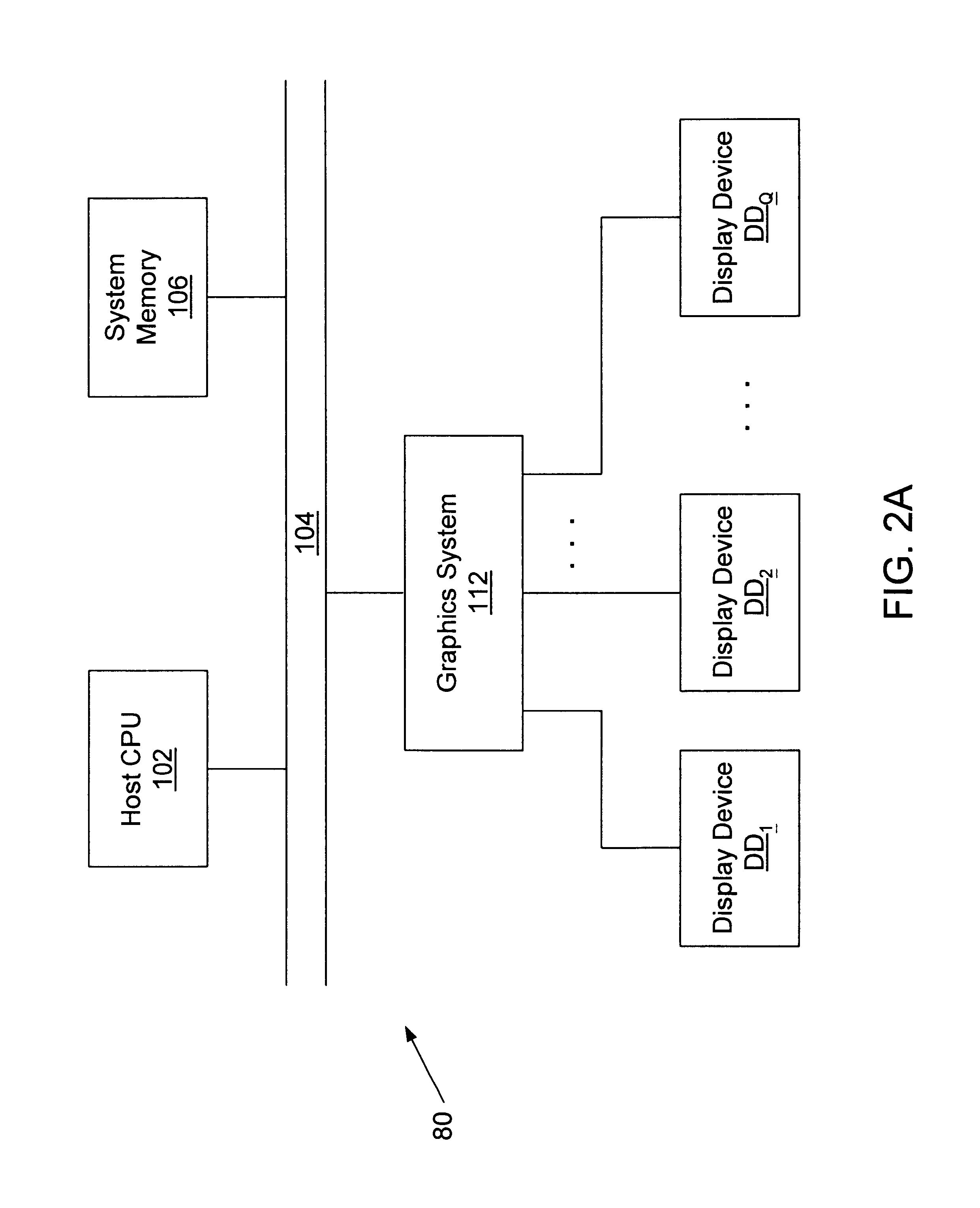
[0064]In a second embodiment, graphics system 112 comprises graphics boards GB(1) through GB(Q / 2) which couple to display devices DD1-DDQ in a one-to-two fashion as shown in FIG. 2C. In other words, graphics board GB(I) couples to and generates video signals for two display devices DD2I-1 and DD21 where I ranges from 1 to Q / 2.

third embodiment

[0065]In a third embodiment, graphics system 112 comprises graphics boards GB(1) through GB(2Q) which couple to projection devices DD1-DDQ in a two-to-one fashion as shown in FIG. 2D. In other words, graphics boards GB(2I-1) and GB(2I) may be daisy chained together to generate a video signal for display device DD1.

[0066]A wide distribution of “mappings” between graphics boards and display devices are possible. At one end of the distribution, a single graphics board may drive all Q display devices, where the size of Q is limited by the computational bandwidth of the graphics board. At the other end of the distribution, X graphics boards may drive a single projection device. The size of integer X is determined by the input video bandwidth of the projection device. The X graphics boards may be daisy-chained together, and partition the effort of generating the video signal for the single projection device.

[0067]In addition, X graphics boards may map to Q projection devices where neither...


PUM


Abstract

A dithering system comprising a dithering unit, a storage medium, and an averaging unit. The dithering unit is configured to receive a set of data values, to add dither values to the data values, and to truncate the resultant addition values to L-bit truncated values. The storage medium is configured to store the L-bit truncated values. The averaging unit is configured to read the L-bit truncated values from the storage medium, and to compute an average value using at least a subset of the L-bit truncated values. The dither values may have an average value of approximately one-half. The dither values may approximate a uniform distribution of numbers between −A+½ and A+½, wherein A is greater than or equal to one. Alternatively, the dithering unit may receive a temporal stream of data values, and the average unit may perform a temporal average (e.g. an FIR filter). The dithering system may be incorporated in a graphics system. In this case, data values may represent rendered sample values (e.g. color or alpha).

Description

CROSS-REFERENCE TO RELATED APPLICATIONS[0001]This application claims the benefit of U.S. Provisional Application No. 60 / 214,597, filed on Jun. 27, 2000, and titled “Recovering Added Precision from L-Bit Samples by Dithering the Samples Prior to an Averaging Computation”.[0002]This application claims the benefit of U.S. Provisional Application No. 60 / 175,384, filed on Jan. 11, 2000, and titled “Photorealistic Hardware Antialiasing”.BACKGROUND OF THE INVENTION[0003]1. Field of the Invention[0004]This invention relates generally to the field of digital signal processing and, more particularly, to a system and method for operating on data values so that their average (with respect to time and / or space) survives truncation.[0005]2. Description of the Related Art[0006]Modern computer systems typically rely on a graphics system to generate output video signals for the display devices. Early graphics systems were only responsible for receiving data produced by the host processor and display...

Claims


Application Information

Patent Timeline
Patent Type & Authority Patents(United States)
IPC IPC(8): G06K9/40G09G5/02G06K15/00
CPCG06T15/005G09G5/02G09G5/397G09G5/14G09G2340/10G09G2340/0428
Inventor DEERING, MICHAEL F.NAEGLE, N. DAVIDNELSON, SCOTT R.
Owner ORACLE INT CORP
Learn More