
Method and system of data packet transmission timing for controlling bandwidth

a technology of data packet transmission and bandwidth control, applied in the direction of time-division multiplex, multiplex communication, electrical apparatus, etc., can solve the problems of unreliable protocols, automatic re-transmission of lost or corrupted packets, and various problems

Inactive Publication Date: 2012-05-08
RATEZE REMOTE MGMT LLC
View PDF38 Cites 0 Cited by
  • Summary
  • Abstract
  • Description
  • Claims
  • Application Information

AI Technical Summary

Benefits of technology

[0025]In a preferred embodiment of the invention, the precision of the bandwidth control is maximized by the use of the highest resolution clock or other timing device available at the sending device. This provides the best compensation for wait time rounding errors.
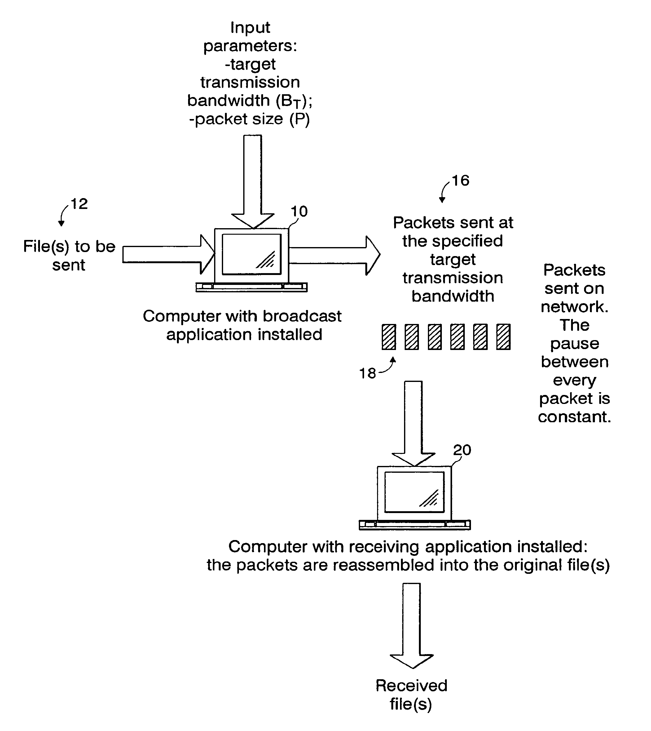
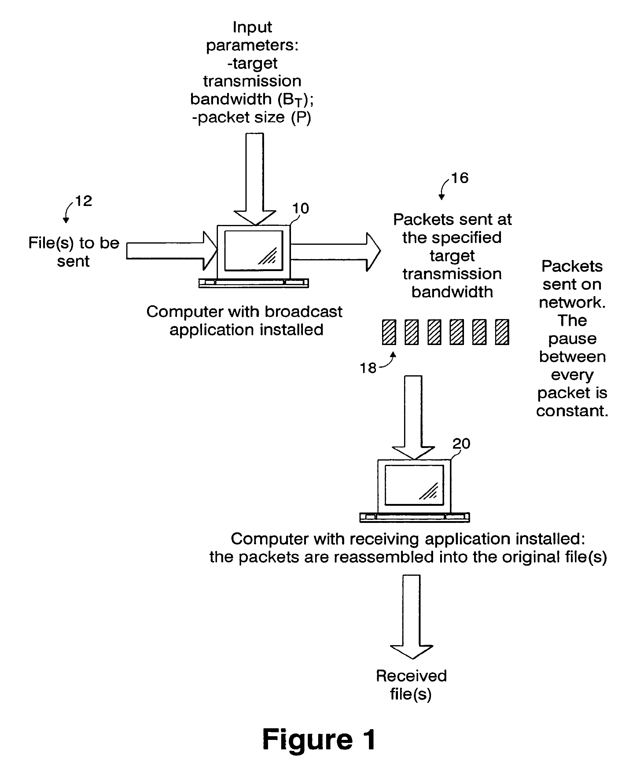
[0028]As compared to the existing transmission problem solutions discussed above, the invention causes data flow to tend towards target bandwidth, decreasing or increasing transmission speed as necessary. Also, the invention provides traffic control at the source so that the outgoing traffic is smoothly distributed and tends towards the target bandwidth. Further, the invention prevents excess packets by introducing pauses between packets, blocking the sender until the next packet is to be transmitted and never discards packets. Also, the present invention maintains a constant bandwidth usage with minimal burstiness.

Problems solved by technology

Some protocols may be considered to be “unreliable”, herein meaning any transmission protocol that provides best-effort delivery of packets, and in particular, does not perform automatic re-transmission of lost or corrupted packets.
If data is sent without a precise bandwidth control, various problems can arise.
The problems caused by the different scenarios described above can adversely affect different components and structures of the system that receive the data, such as routing and switching devices and the destination receiver devices.
(1) Sending data packets too fast.
Broadcasting of the data at a speed above the target bandwidth usually results in substantial packet losses.
Loss of packets reduces the integrity of the data transmission.
Also, too high a transmission speed can cause congestion if routing devices are not able to buffer the incoming data stream.
The same problem can affect encapsulators if data is sent to a satellite uplink.
Here, entire series of packets can be lost.
At the receiving device side, packet reassembly can be difficult if the hardware or application program processing the received data is not designed for an incoming data stream speed higher than the bandwidth mean (average) value.
Moreover, a local area network (LAN) to which the receiving devices are connected can experience congestion if no traffic buffering mechanism is provided between the data transmitter and the receiving devices.
(2) Sending data packets too slow.
However, a resource waste is caused, especially if the connection between the data transmitter and receiving devices is purchased on a bandwidth usage basis instead of on a transmitted data amount basis.
Also, audio and video streaming quality can be affected if the receiving data rate is too low.
That is, the received sound and video will be intermittent, garbled, or otherwise distorted
Even when the average output transmission bandwidth is close to the target bandwidth does not always guarantee that the data stream will be free of problems.
As a result, the same problems described above for transmissions with mean bandwidth higher or lower than the target bandwidth can arise, although the adverse affects are experienced to a lesser degree.

Method used


Image

  • Method and system of data packet transmission timing for controlling bandwidth
  • Method and system of data packet transmission timing for controlling bandwidth
  • Method and system of data packet transmission timing for controlling bandwidth

Examples


Embodiment Construction

[0039]In the transmission of data packets, bandwidth is usually defined as the amount of data transmitted in a given time frame. Bandwidth control refers to the capability to control the bandwidth, i.e., the rate of transmission for a given amount of data. A significant value to evaluate bandwidth control quality is the mean (or average) bandwidth BM, that is, the arithmetic mean value about which the actual transmission rate centers during the entire transmission. The target bandwidth BT is defined as the needed (selected) bandwidth for a given content transmission. In some cases, BT is an amount of bandwidth that is sold or leased to a content producer by a broadcast facility.

[0040]If BT is known, the mean bandwidth BM can be defined by the following equation:

(BT−ε)BMBT+ε)  (Equation 1-1)

where

[0041]BT=the target bandwidth

[0042]BM=mean bandwidth

[0043]ε=error or deviation of BM from BT

[0044]The main goal of bandwidth control is to minimize the error ε between BM and BT. To consider...


PUM


Abstract

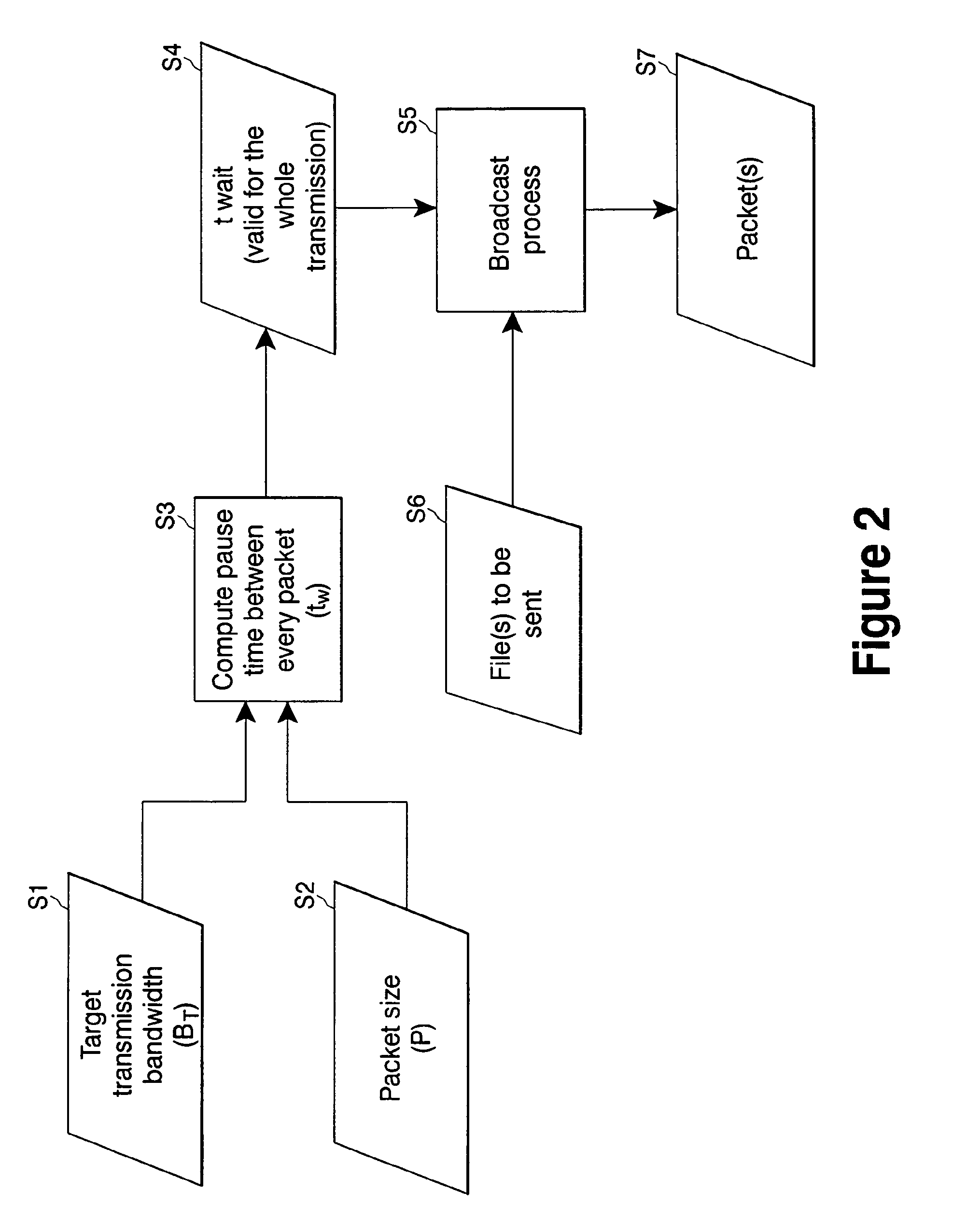
A method and system for determining a wait time (tw) to be used between successive transmissions of packets of a content to achieve a selected target bandwidth BT for the transmission. The wait time between successive packets of a content being transmitted is determined as a function of the selected target bandwidth (BT) to be achieved during the transmission and the size (P) of the packets based on the algorithmtw=PBTThe invention provides bandwidth control at the source (the sending device) without relying on network Quality of Service (QoS) facilities.

Description

CROSS-REFERENCES TO RELATED APPLICATIONS[0001]This application is a continuation application of commonly assigned U.S. patent application Ser. No. 10 / 062,830, filed on Jan. 31, 2002, and entitled “METHOD AND SYSTEM OF DATA PACKET TRANSMISSION TIMING FOR CONTROLLING BANDWIDTH,” which is hereby incorporated herein in its entirety by reference.FIELD OF THE INVENTION[0002]The invention relates to a method and system for timing the transmission of data packets from a sender device to one or more receiving devices, for achieving bandwidth control.BACKGROUND OF THE INVENTION[0003]In performing data transmission using various media such as cable, telephone line, satellite communication, etc., it is conventional for the data to be sent from one device to other devices. The data is first fragmented, or segmented, into packets and then the packets transmitted, or broadcast. The term “packet” is used to indicate a sequence of bytes and represents the smallest unit of transmission and reception....

Claims


Application Information

Patent Timeline
Patent Type & Authority Patents(United States)
IPC IPC(8): H04J3/16H04L47/20
CPCH04L47/10H04L47/22H04L47/28H04L47/38
Inventor MARCHETTO, JARNOEMANUELO, LA COGNATA
Owner RATEZE REMOTE MGMT LLC
Learn More