Paint tray trolley

a tray trolley and paint technology, applied in the field of paint accessories, can solve the problems of significant strain on the lower back and risk of work-related injuries, and achieve the effect of convenient movement of the tray

Inactive Publication Date: 2008-09-16
BIEBEL DAVID R
View PDF3 Cites 19 Cited by
  • Summary
  • Abstract
  • Description
  • Claims
  • Application Information

AI Technical Summary

Benefits of technology

[0001]The present invention is in the field of painting accessories. More particularly, the present invention is directed to a trolley for a paint tray to permit a painter to easily move the tray from place to place without having to stoop and pick it up.

Problems solved by technology

The problem, then, becomes stooping to pick up the paint tray and move it from place to place as the painting progresses.
This puts significant strain on the lower back and risks a work-related injury.

Method used


Image

  • Paint tray trolley
  • Paint tray trolley
  • Paint tray trolley

Examples


Embodiment Construction

)

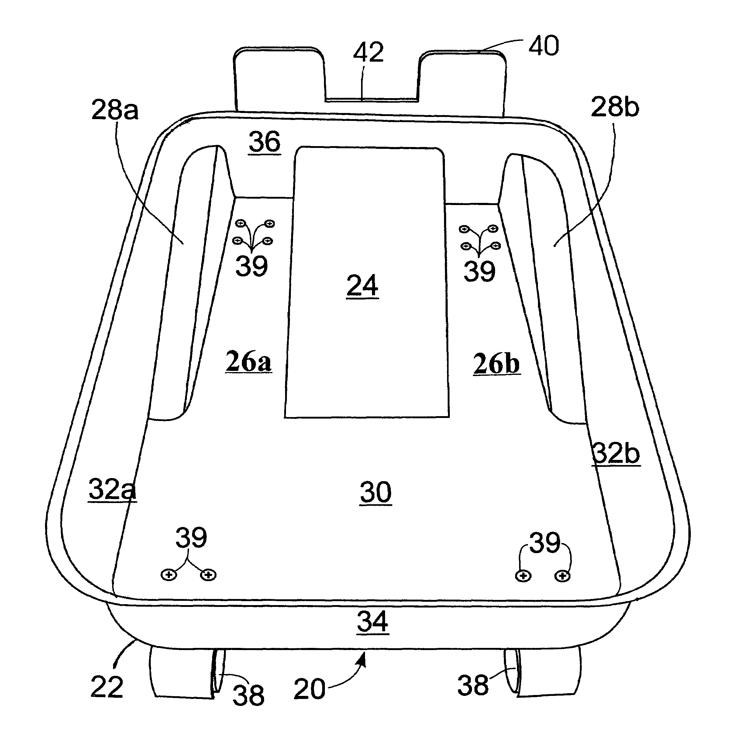
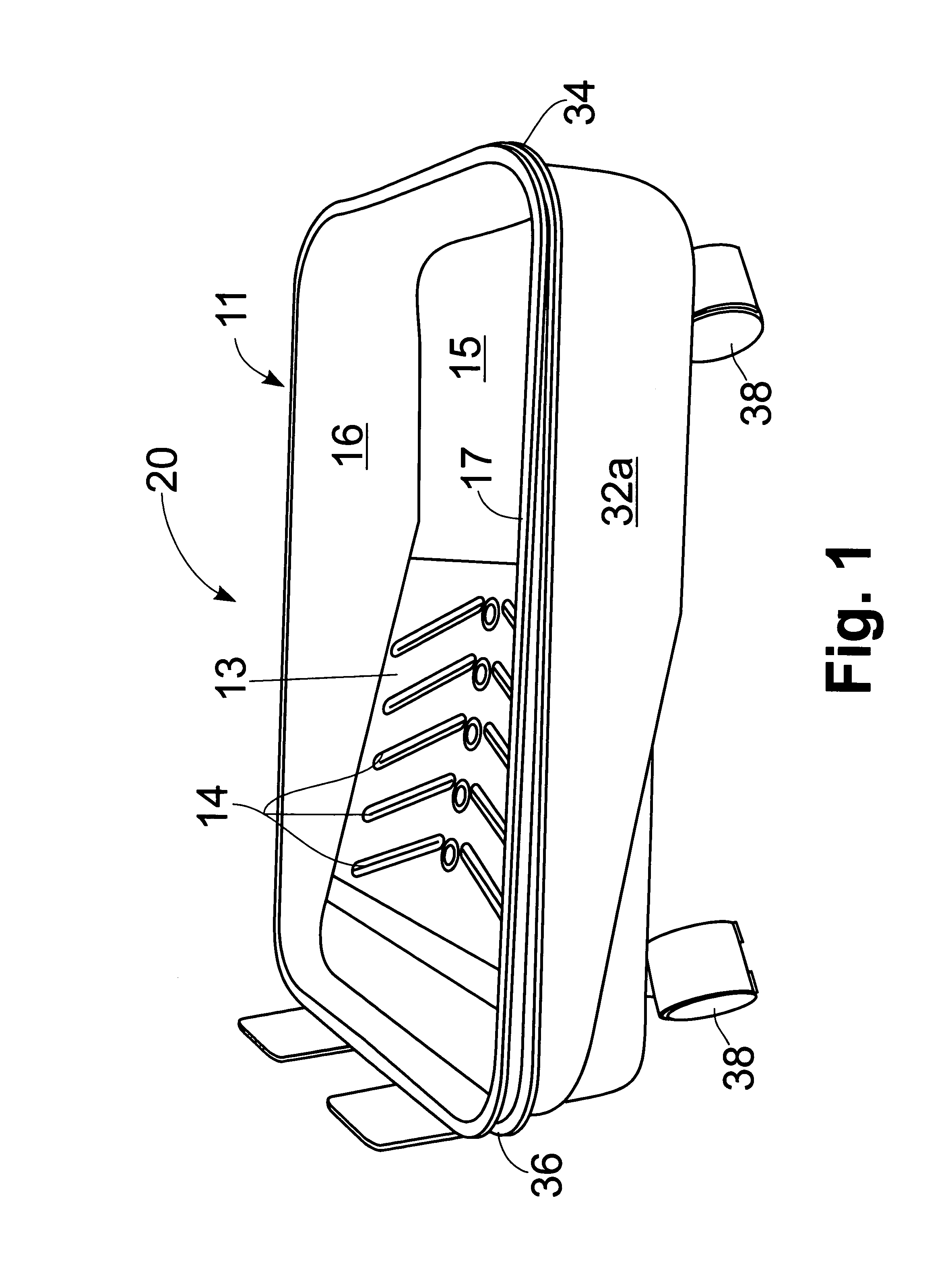
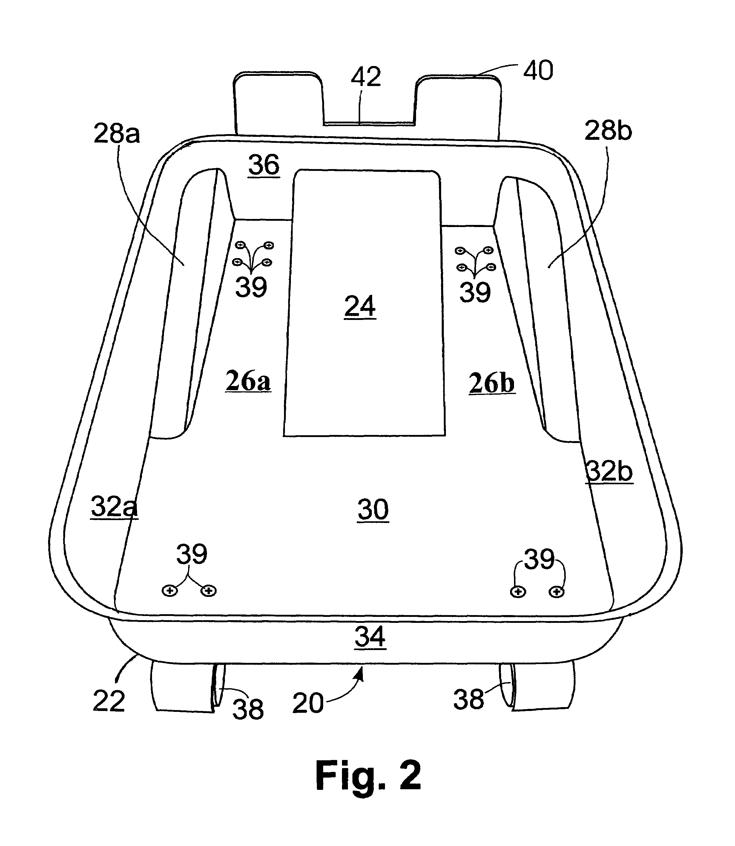
[0012]The paint tray trolley of the present invention is depicted in FIGS. 1-3 generally at 20. Trolley 20 includes a base 22 which receives paint tray 11. Paint tray 11 is a conventional paint tray with a sloping bottom 13 with ribs 14, flat bottom portion 15, upwardly extending sides 16 and ends 17 with two downwardly projecting clips or feet 18 which serve to level tray 11 when it is sitting on a flat surface and permit the tray 11 to be clipped to the step of a ladder. It is noted that the clips 18 are typically inadequate to support the weight of the paint-ladened tray 11 and wind up spilling the tray's contents in the most undesirable spots, another good reason to find an alternative to painting from a ladder.

[0013]Base 22 has a first downwardly sloping floor portion 24 (FIG. 2) which underlies at least a portion of the sloping bottom 13. Slot means 26a and 26b are provided to accommodate the clips 18, with first downwardly sloping floor portion 24 lying intermediate slot mea...


PUM


Abstract

A base is equipped with wheels to receive a paint tray with stabilizing feet and enable the tray to be moved from place to place without the need to pick it up. An upwardly extending flange can be engaged by the paint roller to push/pull it to a new location.

Description

BACKGROUND AND SUMMARY OF THE INVENTION[0001]The present invention is in the field of painting accessories. More particularly, the present invention is directed to a trolley for a paint tray to permit a painter to easily move the tray from place to place without having to stoop and pick it up.[0002]Professional painters and the more experienced do-it-yourselfers use 1 gallon paint trays, rather than the smaller 1 quart variety. When doing a big job, the workman is able to spend more time painting walls, ceilings, etc., and less time opening and resealing cans. In addition, the painting professional utilizes an extensible handle for her / his roller and stands on the floor so as to avoid climbing up and down a ladder. Again, this enables the painter to make better use of her / his time. The problem, then, becomes stooping to pick up the paint tray and move it from place to place as the painting progresses. This puts significant strain on the lower back and risks a work-related injury.[00...

Claims


Application Information

Patent Timeline
Patent Type & Authority Patents(United States)
IPC IPC(8): B65D21/02
CPCB44D3/126
Inventor BIEBEL, DAVID R.
Owner BIEBEL DAVID R
Why Eureka
Try Eureka