
Comfort belt spring pulley

a technology of comfort belt and pulley, which is applied in the direction of chairs, vehicle components, vehicle arrangements, etc., can solve the problems of distress or discomfort of seat occupants, non-uniform support, and belts that do not provide uniform support to seat occupants, so as to reduce the force required to engage the traction element

Active Publication Date: 2008-09-16
SCHUKRA OF NORTH AMERICA
View PDF62 Cites 35 Cited by
  • Summary
  • Abstract
  • Description
  • Claims
  • Application Information

AI Technical Summary

Benefits of technology

"The invention is an ergonomic device for a seat that provides uniform support and adjustment through a pulley and traction element. The device includes a hinge and at least one pulley connected to the side plates, allowing for easy engagement with the traction element. The device also includes a spinal relief zone to avoid uncomfortable pressure on the spine. Additionally, the invention includes a two-part belt that reduces complexity and costs of manufacture. The invention can be used as a lumbar support for a seat with a seat back frame. The technical effects of the invention include improved comfort, adjustability, and reduced pressure on the spine."

Problems solved by technology

When the belt or strap is adjusted only on one side, the belt does not provide uniform support to the seat occupant.
Non-uniform support often leads to distress or discomfort of the seat occupant after a period of time.
That is, the bony vertebrae of the spine become uncomfortable if direct pressure is applied to them by a lumbar support pressure surface.

Method used


Image

  • Comfort belt spring pulley
  • Comfort belt spring pulley
  • Comfort belt spring pulley

Examples


second embodiment

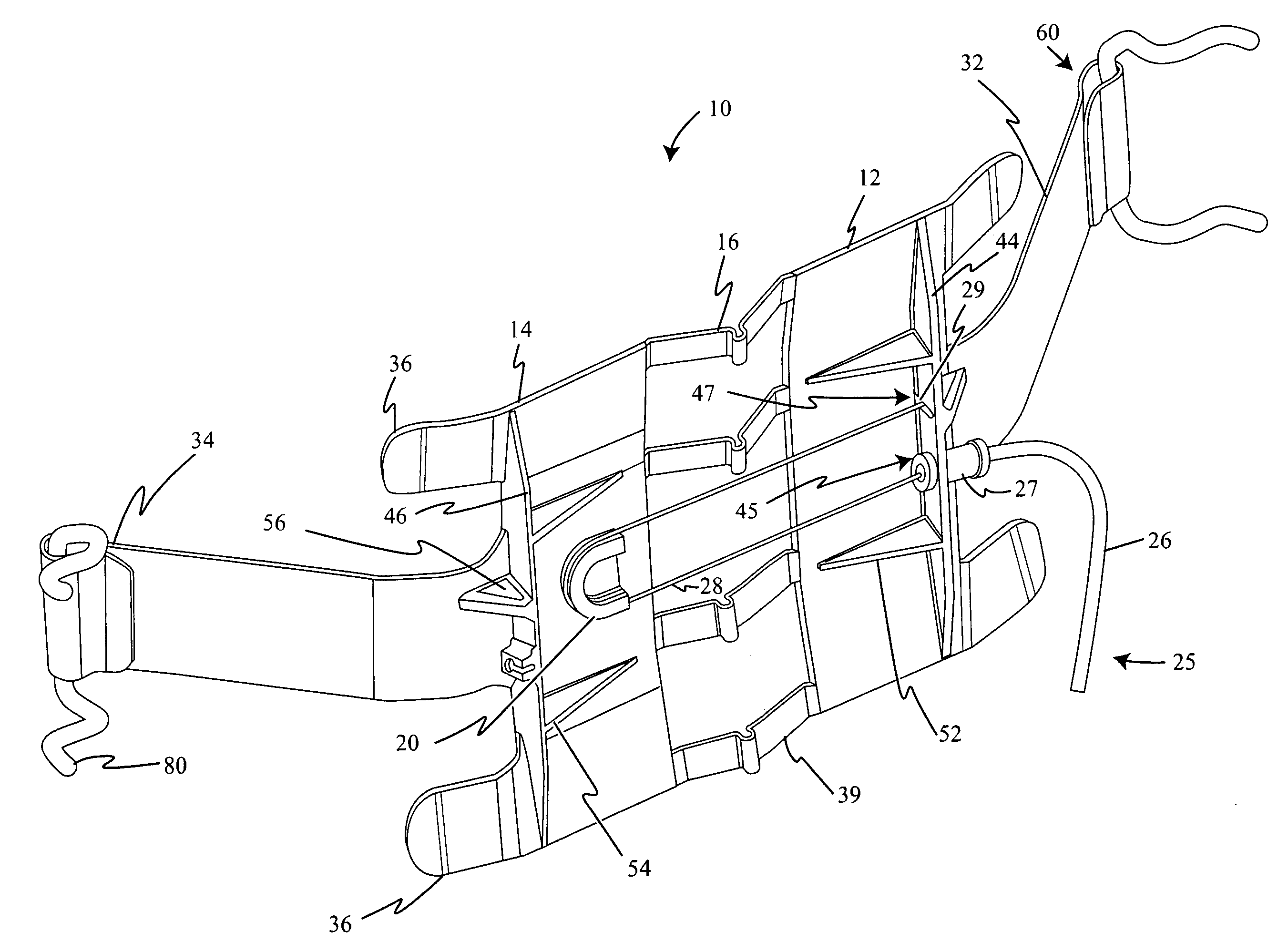
[0043]FIG. 3 illustrates the belt, generally indicated by numeral reference 110. The belt 110 includes a first side plate 112, a second side plate 114, a hinge 116, a first pulley 120, and a traction element 125. In the embodiment depicted in FIG. 3, the first pulley 120 is rotatably mounted to the second side plate 114. As an example, the first pulley 120 may be mounted through the use of a pin or rivet 121 such that the first pulley 120 rotates about the pin 121. The first pulley 120 may be in the form of a metal or plastic wheel. The traction element 125 includes a cable wire 128 that is at least partially wrapped about the first pulley 120. The traction element 125 is connected to the first side plate 112. In the embodiment depicted in FIG. 3, the traction element 125 is connected to a first rib 144 of the first side plate 112. When a tractive force is applied to the traction element 125, the traction element 125 acts upon the first pulley 120 and the first rib 144 to at least p...

third embodiment

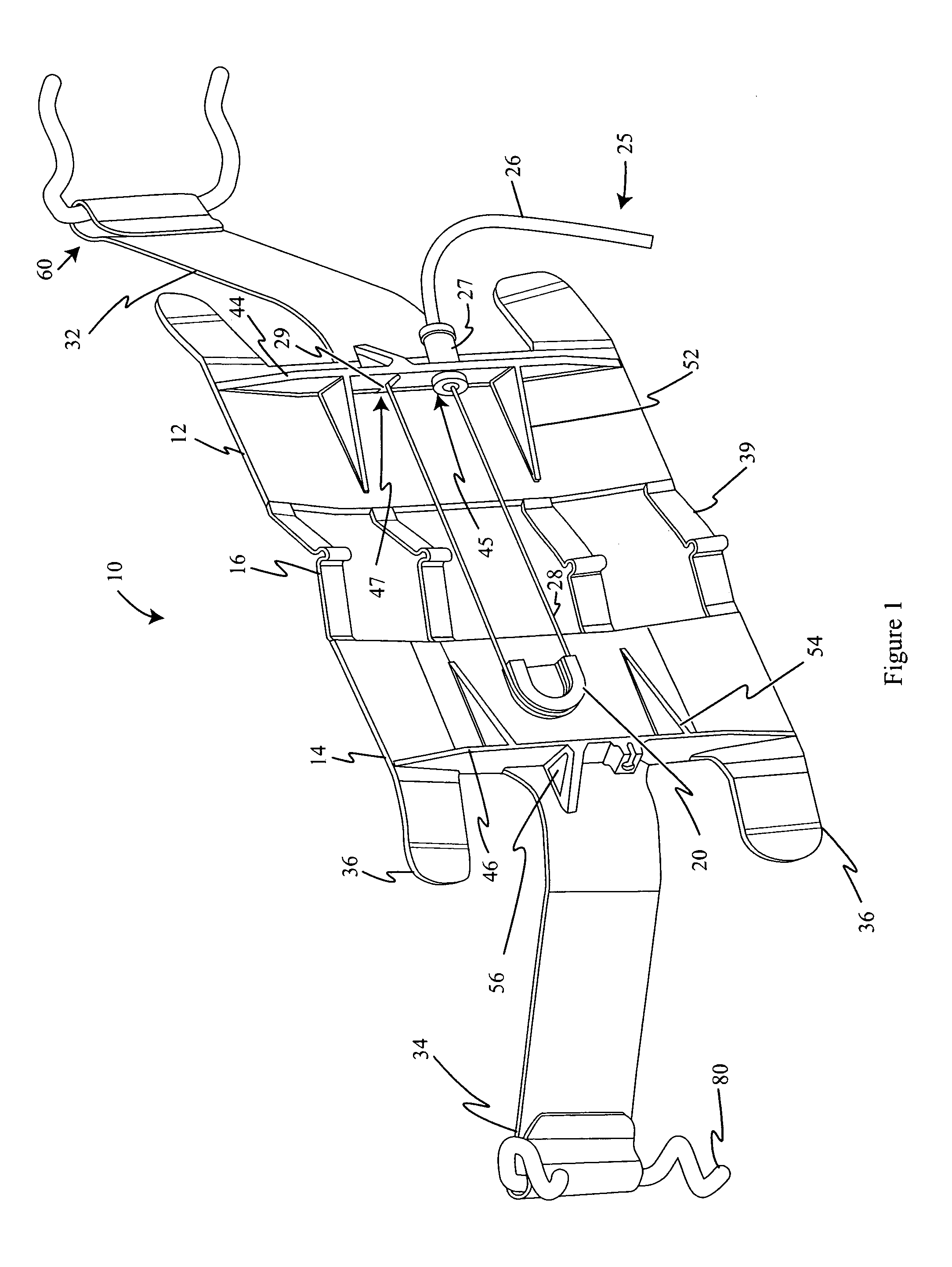
[0044]FIG. 4 illustrates the belt, generally indicated by numeral reference 210. The belt 210 includes a first side plate 212, a second side plate 214, a hinge 216, a first pulley 220, a second pulley 222, a traction element 225, a first rib 244, and a second rib 246. The first pulley 220 is attached to the second side plate 214, and the second pulley 222 is attached to the first side plate 212. In the embodiment depicted in FIG. 4, the first pulley 220 is integrally formed or molded as part of the second side plate 214, and the second pulley 222 is integrally formed or molded as part of the first side plate 212. However, the pulleys 220, 222 could equally be rotatably mounted to the side plates 212, 214. The traction element 225 includes a sleeve 226, a cable fastener 227, a cable wire 228, and a cable end 229. The cable end 229 is connected to the second side plate 214, and the cable fastener 227 connects the sleeve 226 to the first side plate 212. In the embodiment depicted in FI...

fourth embodiment

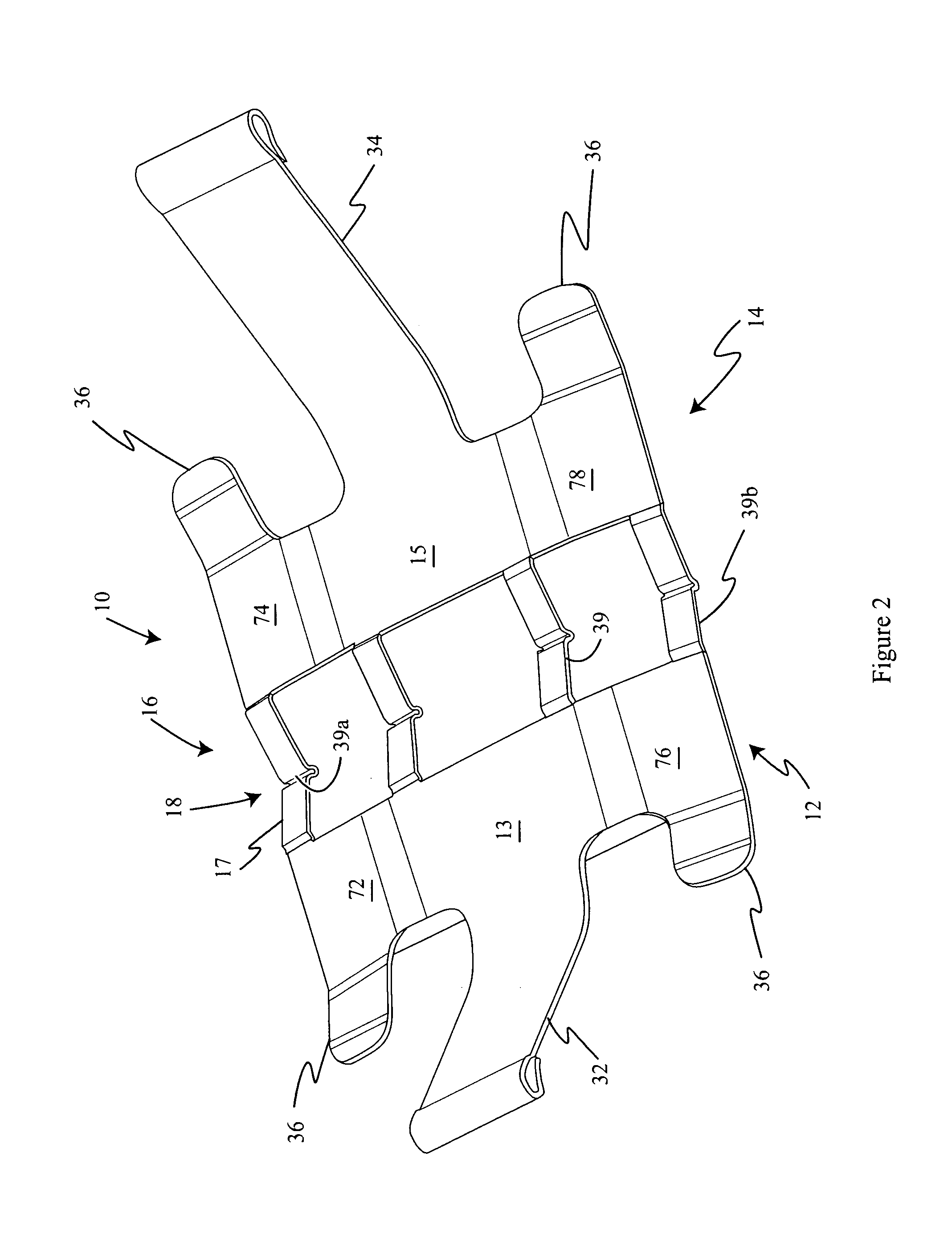
[0045]FIG. 5 illustrates the belt. The belt 310 includes a first side plate 312, a second side plate 314, a hinge 316, a first pulley 320, a second pulley 322, a traction element 325, a first rib 344, and a second rib 346. The first pulley 320 is connected to the second side plate 314 through the use of a first pulley spring 350, and the second pulley 322 is connected to the first side plate 312 through the use of a second pulley spring 351. The springs 350, 351 greatly improve the crashworthiness of the belt 310. In the embodiment depicted in FIG. 5, the springs 350, 351 connect the pulleys 320, 322 to the respective side plate 312, 314 at the ribs 344, 346. In other words, the first pulley 320 is connected to the second rib 346 via the first pulley spring 350, and the second pulley 322 is connected to the first rib 344 via the second pulley spring 351.


PUM


Abstract

An ergonomic device for a seat is disclosed. The ergonomic device includes a first side plate and a second side plate spaced apart from the first side plate. A hinge connects the second side plate to the first side plate. The ergonomic device also includes at least one pulley connected to the first side plate or the second side plate. A traction element is connected to at least one of the side plates, and the traction element has a cable wire generally wrapped about the at least one pulley. The traction element engages the pulley to at least partially collapse the hinge when a tractive force is applied to the traction element.

Description

CROSS-REFERENCE TO RELATED APPLICATIONS[0001]None.BACKGROUND OF THE INVENTION[0002]1. Field of the Invention[0003]The present invention relates to ergonomic devices for vehicle seats and more particularly to belt-type ergonomic devices.[0004]2. Related Art[0005]Vehicle seats typically include one or more ergonomic device, such as a lumbar support. Belt-type ergonomic devices are a common type of vehicle seat ergonomic device. The belt-type ergonomic device generally includes an adjustable belt or strap. The belt supports the vehicle seat occupant and is adjusted to vary the effective length or stiffness of the support.[0006]Previously, belt-type ergonomic devices adjusted only on one side or included complex devices for bi-lateral adjustment. When the belt or strap is adjusted only on one side, the belt does not provide uniform support to the seat occupant. Non-uniform support often leads to distress or discomfort of the seat occupant after a period of time.[0007]Furthermore, in the...

Claims


Application Information

Patent Timeline
Patent Type & Authority Patents(United States)
IPC IPC(8): A47C7/46
CPCB60N2/66A47C7/465B60N2/6671
Inventor MCMILLEN, ROBERT J.
Owner SCHUKRA OF NORTH AMERICA
Learn More