Embossing device

a technology of embossing roller and embossing roller, which is applied in the field of embossing roller, can solve the problems of high production cost, high cost of embossing roller, and embossing roller

Inactive Publication Date: 2008-09-23
GD SPA
View PDF9 Cites 15 Cited by
  • Summary
  • Abstract
  • Description
  • Claims
  • Application Information

AI Technical Summary

Benefits of technology

[0008]It is an object of the present invention to provide an embossing device designed to eliminate, at least partially, the aforementioned drawbacks.

Problems solved by technology

The embossing rollers described in Patent Application WO 0230661 A1 are fairly complex and therefore expensive to produce, and must be changed alongside a change in format, so that producing a number of packing materials of different formats calls for a large number of different, high-cost embossing rollers.

Method used


Image

  • Embossing device
  • Embossing device
  • Embossing device

Examples


Embodiment Construction

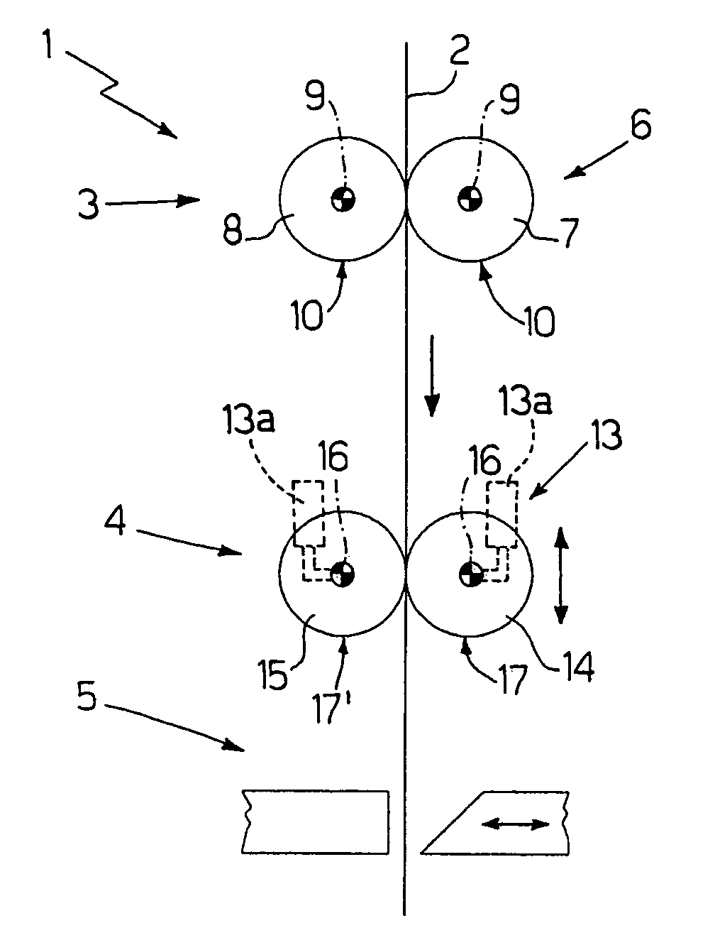
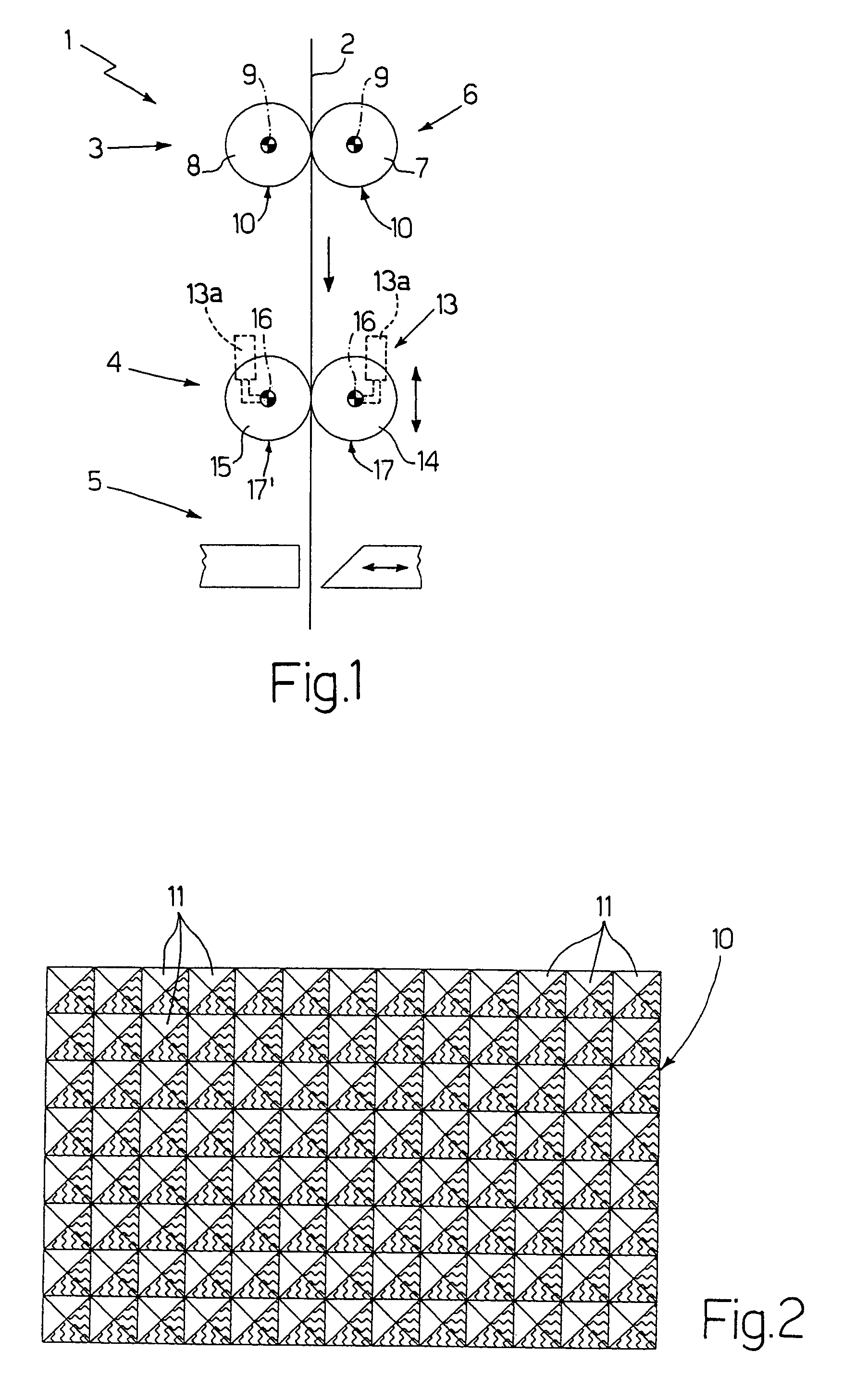
[0021]Number 1 in FIG. 1 indicates as a whole an embossing device for satin finishing a strip of packing material 2 and impressing graphics G (e.g. letters and / or designs—FIG. 10) on the strip of packing material 2.

[0022]Device 1 comprises a feed unit (not shown) for feeding the strip of packing material 2 along a given path through an embossing station 3, an embossing station 4 downstream from embossing station 3, and a cutting station 5 downstream from embossing station 4 and where a cutting unit cuts the strip of packing material 2 transversely into portions B of satin finished packing material 2 (FIG. 10).

[0023]Device 1 also comprises an embossing unit 6 located at embossing station 3 and for satin finishing packing material 2.

[0024]Embossing unit 6 comprises two embossing rollers 7 and 8, each having a respective axis of rotation 9, and a respective longitudinal outer surface 10 substantially parallel to respective axis of rotation 9. Axes of rotation 9 are substantially parall...


PUM

PropertyMeasurementUnit
areaaaaaaaaaaa
areasaaaaaaaaaa
shapeaaaaaaaaaa

Abstract

An embossing device having a first embossing unit for satin finishing a strip of packing material, and a second embossing unit for impressing graphics on the strip of packing material; the second embossing unit has two embossing rollers, at least one of which only has embossing pins in areas for impressing the graphics.

Description

[0001]The present invention relates to an embossing device.[0002]The present invention may be used to particular advantage in the manufacture of packets of cigarettes, to which the following description refers purely by way of example.BACKGROUND OF THE INVENTION[0003]Packing material is known to be embossed or satin finished by feeding it between two embossing rollers, each of which has an outer surface with a number of impression pins which cooperate with the impression pins on the other roller to satin finish the packing material.[0004]Patent Application WO 0230661 A1 describes an embossing device, in which a roller comprises pins of different geometric shapes, and the difference in shape of the pins provides for impressing graphics on the packing material.[0005]The embossing rollers described in Patent Application WO 0230661 A1 are fairly complex and therefore expensive to produce, and must be changed alongside a change in format, so that producing a number of packing materials o...

Claims


Application Information

Patent Timeline
Patent Type & Authority Patents(United States)
IPC IPC(8): B41F19/02B31F1/07
CPCB31F1/07B31F2201/0733B31F2201/0743B31F2201/0753Y10T156/1023B31F2201/0792B31F2201/0794B65B19/228B65B61/025B31F2201/0774
Inventor SPATAFORA, MARIO
Owner GD SPA
Why Eureka
Try Eureka