Floating berth modular dock system assembly

a floating dock and modular technology, applied in vessel construction, special-purpose vessels, transportation and packaging, etc., can solve the problems of unsuitable dual-use devices, unstable structures for pedestrian traffic, and unsuitable decks or walkways, etc., to achieve the effect of increasing the safety of the devi

Active Publication Date: 2008-09-23
MARINE IP
View PDF18 Cites 37 Cited by
  • Summary
  • Abstract
  • Description
  • Claims
  • Application Information

AI Technical Summary

Benefits of technology

[0029]Still yet another objective of the instant invention is to provide a kit for use with pre-existing drive-on dock structures for increasing the safety thereof.

Problems solved by technology

These devices work relatively well for docking large watercraft however, the upwardly extending hull guides and cylindrically shaped upper surface make these devices generally unsuitable for dual use as decks or walkways.
The open center does not provide sufficient guiding for several types of boat hulls.
In addition, the narrow width of the arms, the lack of connection to floatation units on tour sides, the open center, and the low buoyancy of the small cubes make these structures extremely unstable for pedestrian traffic and unsuitable for decks or walkways.
This safety hazard is magnified when the docks are used at night.
Still further, the open nature of these docks combined with the wave action associated with large bodies of water often results in repeated splashing of water into the drive units of the docked watercraft and thus causes premature failure of important components of the watercraft drive system.

Method used


Image

  • Floating berth modular dock system assembly
  • Floating berth modular dock system assembly
  • Floating berth modular dock system assembly

Examples


Embodiment Construction

[0050]It is to be understood that while a certain form of the invention is illustrated, it is not to be limited to the specific form or arrangement of parts herein described and shown. It will be apparent to those skilled in the art that various changes may be made without departing from the scope of the invention and the invention is not to be considered limited to what is shown in the drawings and described in the specification.

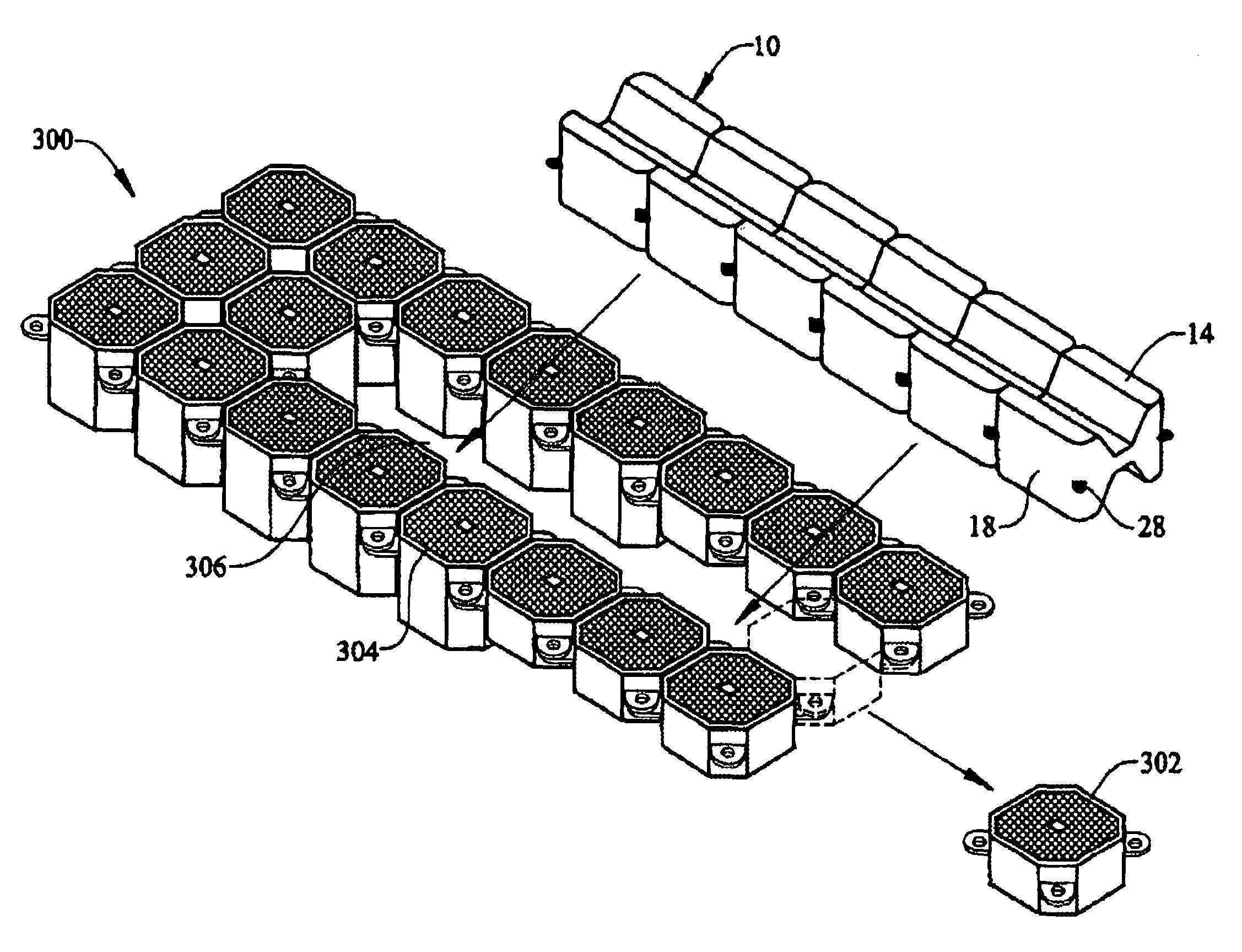
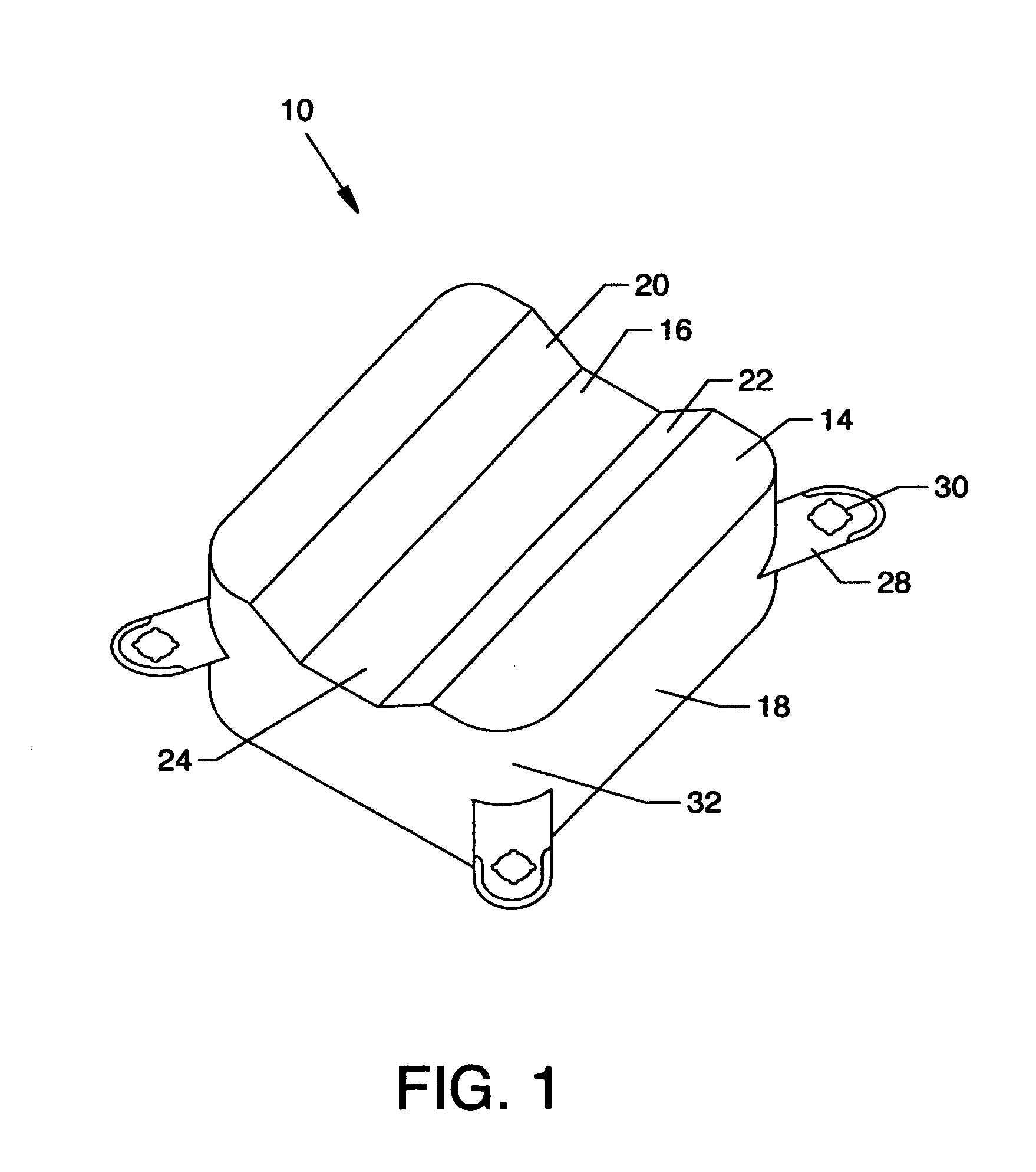
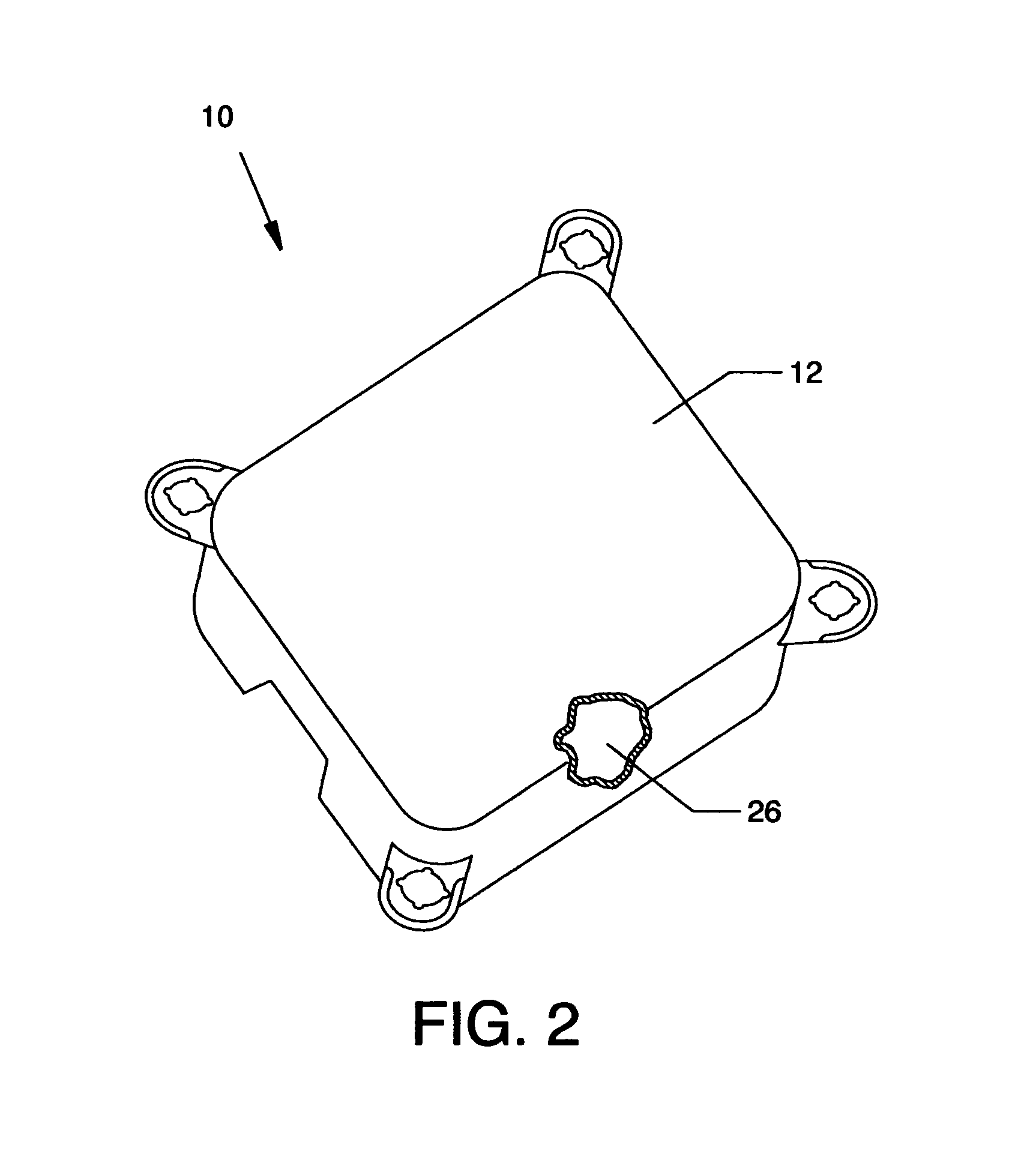
[0051]With reference to FIGS. 1 and 2, the instant invention provides a multidirectional floating element 10. The floating element 10 in its preferred embodiment is a polyhedron in overall shape, including a first generally planar surface 12, a second guiding surface 14 having a Vshaped channel 16 and a plurality of side walls 18 for adjoining and maintaining spacing between the first surface and the second surface. In operation, the first surface 12 is generally arranged to face upwardly for use in constructing floating walkways, floating decks and the lik...


PUM


Abstract

A floating boat lift has a platform, first and second parallel spaced apart arms and a boat holding region defined therebetween, the defined boatholding region having a linking strip of half-blocks with an aligned groove for accepting and guiding a boat keel. The lift includes adjustable buoyancy.

Description

[0001]This application is a continuation-in-part of Ser. No. 10 / 779,477, filed Feb. 12, 2004 and entitled “Multidirectional Floating Dock Element” now U.S. Pat. No. 7,213,531. This invention is directed to floating docks and, in particular, to a multidirectional floating dock element especially suited for assembly of floating docks, drive-on docks and floating decks.BACKGROUND OF INVENTION[0002]In the past modular floating docks have been created by the assembly of a number of floating subunits. These subunits include various geometric shapes with planar upper and lower surfaces. The subunits connect together to create docks and walkways having various shapes and sizes based on the consumers needs.[0003]For example, U.S. Pat. Nos. 6,138,599 and 5,947,049 teach a buoyant walkway module for a boatlift. The device includes a plurality of elongated compartments having planar top and bottom surfaces. The device also includes planar ends for connecting the walkways together in an end to e...

Claims


Application Information

Patent Timeline
Patent Type & Authority Patents(United States)
IPC IPC(8): B63B35/44
CPCB63C1/02B63B3/08
Inventor AHERN, ROY
Owner MARINE IP
Why Eureka
Try Eureka