
Clutch mechanism

a technology of clutches and ring rings, which is applied in the direction of friction clutches, clutches, interlocking clutches, etc., can solve the problems of reducing the grasping power of the driver, putting a heavy burden on the driver, and inevitably large spring load, so as to reduce the diameter of the clutch ring, reduce the generation of load, and simple structure

Active Publication Date: 2008-09-30
ADVANCED INNOVATIONAL MACHINERY CORP
View PDF7 Cites 4 Cited by
  • Summary
  • Abstract
  • Description
  • Claims
  • Application Information

AI Technical Summary

Benefits of technology

The system reduces the force needed to operate the clutch lever, allowing more people to drive two-wheeled vehicles regardless of physical strength while maintaining sufficient pressure contact between friction and clutch plates across all engine speeds.

Problems solved by technology

On the other hand, however, since the spring load of the elastic member is determined on the basis of the maximum torque value, the spring load is inevitably large in a case of a motor vehicle in which engine torque is high.
This puts a heavy burden on the driver.
Actually, in driving of a two-wheeled motor vehicle with a high torque engine for a long time, or in driving along a street with a high traffic density which requires gear shiftings repeatedly, driver's grasping power is likely to be susceptible to lowering.
Under these circumstances, those who can enjoy driving of a two-wheeled motor vehicle have been a limited number of people.
Accordingly, due to difficulty in clutch lever operation itself, types of motor vehicles of which driving they can enjoy have tended to be restricted.
By this method, however, it has not been easy to realize accuracy in removing a pressing force applied by the pressure plate to friction plates and ensuring a condition where pressure contact between the friction plates and the clutch plate is surely removed.
Therefore, pressure contact between the friction plates and clutch plates is not necessarily ensured over a whole range of engine speed.
For example, when the engine speed is high, the pressure contact is not ensured.
As described above, it has not necessarily been easy to concurrently satisfy the demand to reduce a force required for operating a clutch lever and the demand to increase a force with which a clutch pressing mechanism presses friction plates, and further, to ensure pressure contact between the friction plates and clutch plates over a whole range of engine speed.

Method used


Image

  • Clutch mechanism
  • Clutch mechanism
  • Clutch mechanism

Examples


embodiment 1

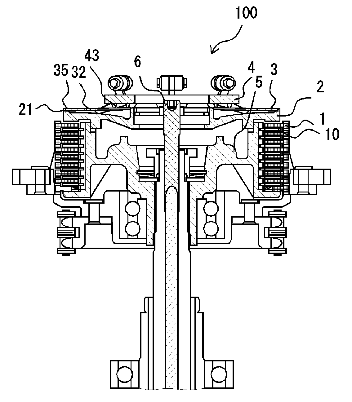
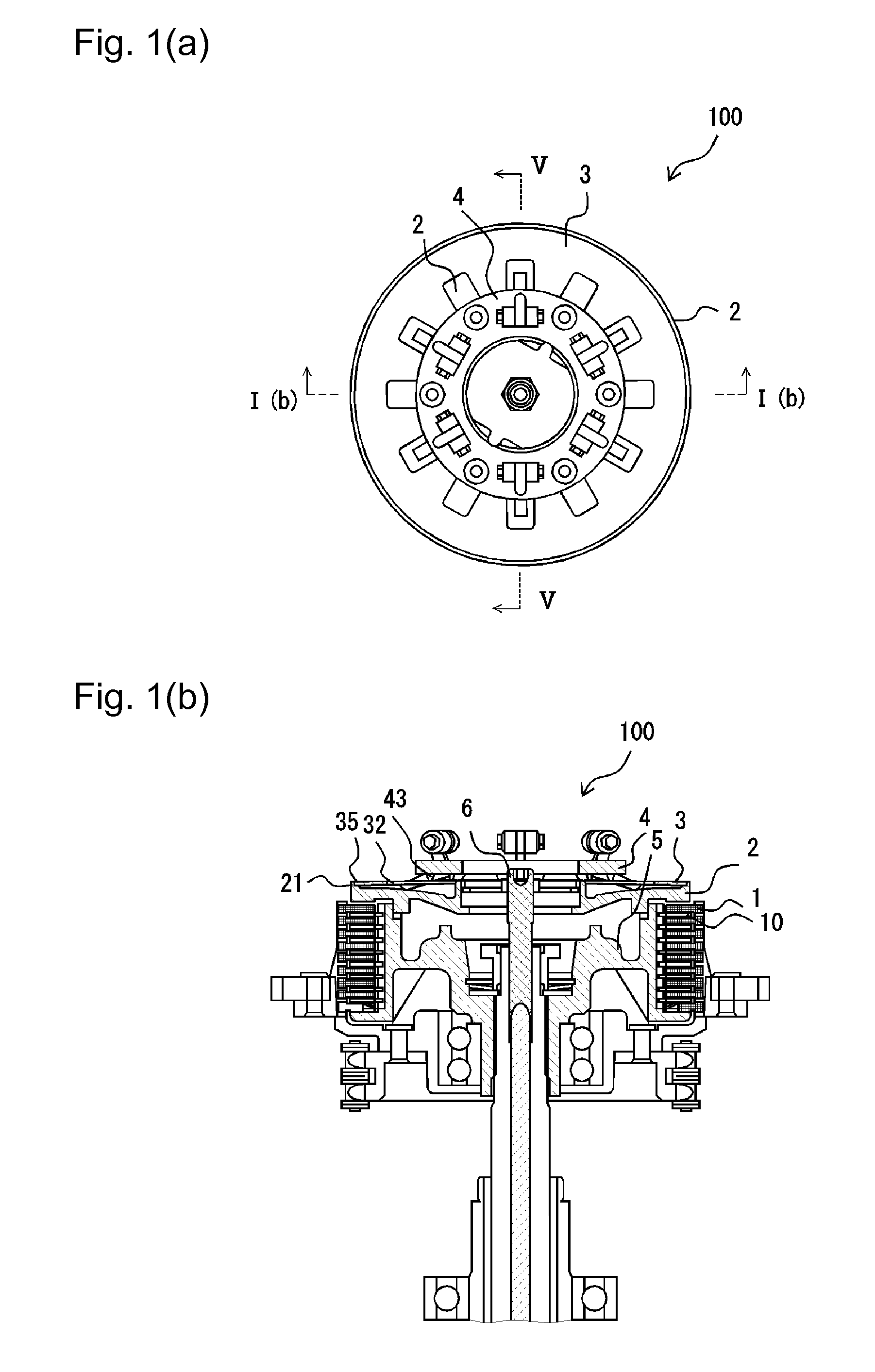
[0051]FIG. 1(a) is a plan view of a clutch mechanism 100 as an embodiment 1 of the present invention, and FIG. 1(b) is a sectional view taken along line I(b)-I(b) in FIG. 1(a).

[0052]The clutch mechanism 100 plays roles to transfer rotational driving force which is inputted via an input system (not shown) to an output system (not shown) and to discontinue the transfer. In this connection, the input system comprises an engine and a series of well-known mechanism parts which are operatively connected to the engine to transfer rotational driving force of the engine to the clutch mechanism 100. The output system comprises a series of well-known mechanism parts which receive the driving force of the engine via the clutch mechanism 100 and output the driving force to power a driving wheel or driving wheels.

[0053]The clutch mechanism 100 has a plurality of friction plates 1 as rotational driving force outputting members connected to the input system, a plurality of clutch plates 10 as rotat...

embodiment 2

[0110]FIG. 6(a) is a sectional view of a clutch mechanism 200 as an embodiment 2 of the present invention, and FIG. 6(b) is a plan view of a base plate 7.

[0111]The embodiment 1 has such a structure that the operative portions 45 of the L-shaped arms 44 of the retainer 4 are brought into direct contact with the pressure plate 2 to apply a load to the pressure plate. On the other hand, the clutch mechanism 200 has such a structure that the base plate 7 as a centrifugal load transfer means as shown in FIG. 6(b) is placed between the operative portions 45 of the L-shaped arms 44 and the pressure plate 2, as shown in FIG. 6(a). With respect to the other structural features, this embodiment is the same as the embodiment 1.

[0112]The base plate 7 has an annular portion 71 and plate portions 72 extending outward from the circumferential edge of the annular portion 71.

[0113]The plate portions 72 are located corresponding to, of the slits 34 of the diaphragm spring 3, those 34 which correspond...

embodiment 3

[0116]FIG. 7 is a sectional view of a clutch disc(s) pressing assembly 300 as an embodiment 3 of the present invention.

[0117]As described in the above, each of the clutch mechanism 100 in the embodiment 1 and the clutch mechanism 200 in the embodiment 2 has such a structure that a diaphragm spring is used as an elastic load-applying means. On the other hand, the clutch mechanism 300 in the embodiment 3 uses coil springs 8 as elastic load-applying means. With respect to the other structural features, this clutch mechanism is the same as the clutch mechanism 100.

[0118]A retainer 4 is fixed to an inner hub 5 with bolts 81, and the coil springs 8 are so placed as to surround the bolts 81. By the fixing of the retainer 4, the coil springs 8 are subjected to a load by the retainer 4. The coil springs 8 apply pressing forces to a pressure plate 2 via spring cups 82. In other words, the coil springs 8 are so disposed as to be compressed between the retainer 4 and the pressure plate 2.

[0119]...


PUM


Abstract

A clutch mechanism has rotational driving force outputting members connected to a rotational driving force input system, rotational driving force receiving members connected to a rotational driving force output system, and a pressing mechanism for pressing the rotational driving force outputting members against the rotational driving force receiving members to keep the rotational driving force outputting members and the rotational driving force receiving members in contact with each other. The pressing mechanism has a constant load applying means and a variable load applying means for together generating the pressing force which brings and keeps the rotational driving force outputting members and the rotational driving force receiving members in contact with each other. A value of a load generated by the constant load applying means being set to be less than the maximum non-slide limit, i.e., the maximum of the non-slide limit which is required for keeping the rotational driving force outputting members and the rotational driving force receiving members in contact with each other to transfer the rotational driving force.

Description

TECHNICAL FIELD[0001]The present invention relates to a clutch mechanism which is used in a motor vehicle such as a two-wheeled motor vehicle, a four-wheeled motor vehicle or the like.BACKGROUND ART[0002]A clutch mechanism plays roles to transfer rotational driving force which is inputted via a rotational driving force input system (hereinafter referred to as “input system”) to a rotational driving force output system (hereinafter referred to as “output system”) and to discontinue the transfer. The clutch mechanism has friction plates which are connected to the input system and clutch plates which are connected to the output system and brought into pressure contact with the friction plates. Accordingly, engagement and disengagement between the input system and the output system are effected by bringing the friction plates and the clutch plates into pressure contact with each other and by releasing the friction plates and the clutch plates from the pressure contact, respectively.[000...

Claims


Application Information

Patent Timeline
Patent Type & Authority Patents(United States)
IPC IPC(8): F16D13/54F16D43/12F16DF16D13/52F16D13/70
CPCF16D43/12
Inventor SHIGEMATSU, TAKESHI
Owner ADVANCED INNOVATIONAL MACHINERY CORP
Learn More