Elliptical diffusers used in displays

a technology of elliptical diffusers and displays, which is applied in the field of backlight displays using asymmetric diffusers, can solve the problems of uniform backlighting and degrade display quality

Active Publication Date: 2008-09-30
WAVEFRONT TECH INC
View PDF8 Cites 100 Cited by
  • Summary
  • Abstract
  • Description
  • Claims
  • Application Information

AI Technical Summary

Problems solved by technology

This Moiré pattern destroys the uniformity of the backlighting and degrades the display quality.

Method used


Image

  • Elliptical diffusers used in displays
  • Elliptical diffusers used in displays
  • Elliptical diffusers used in displays

Examples


Embodiment Construction

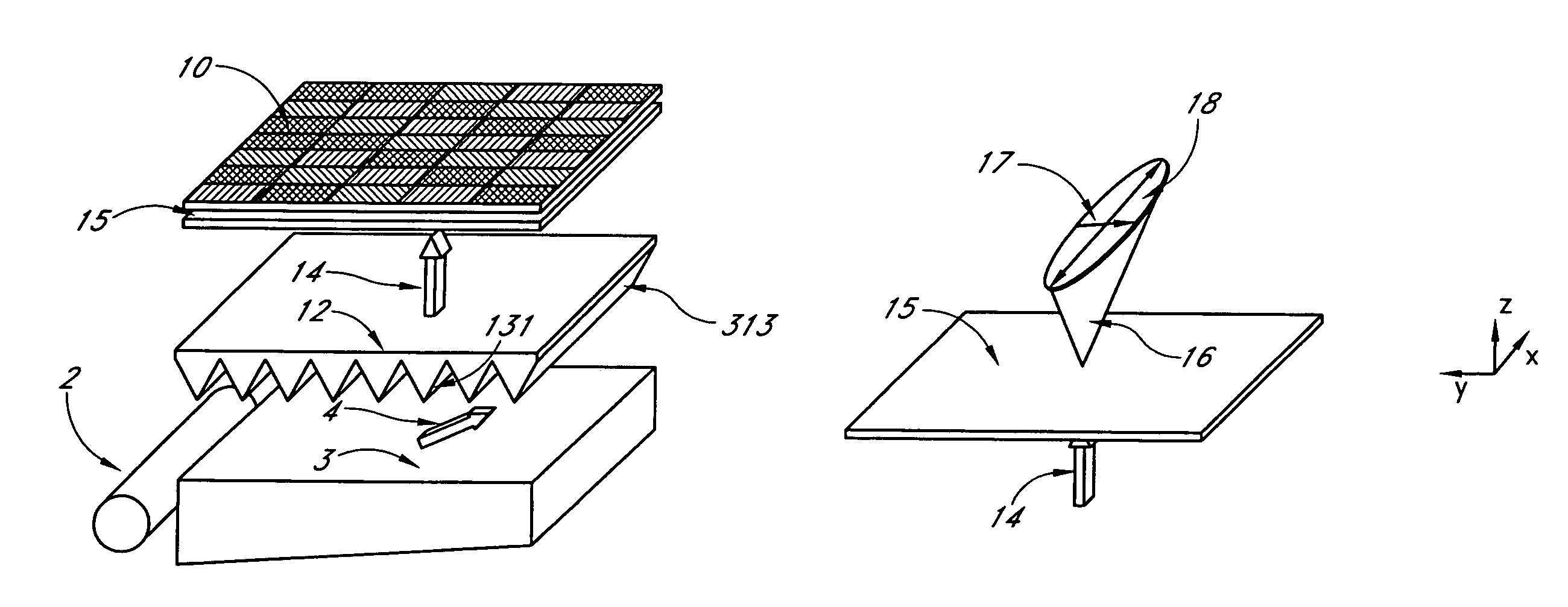
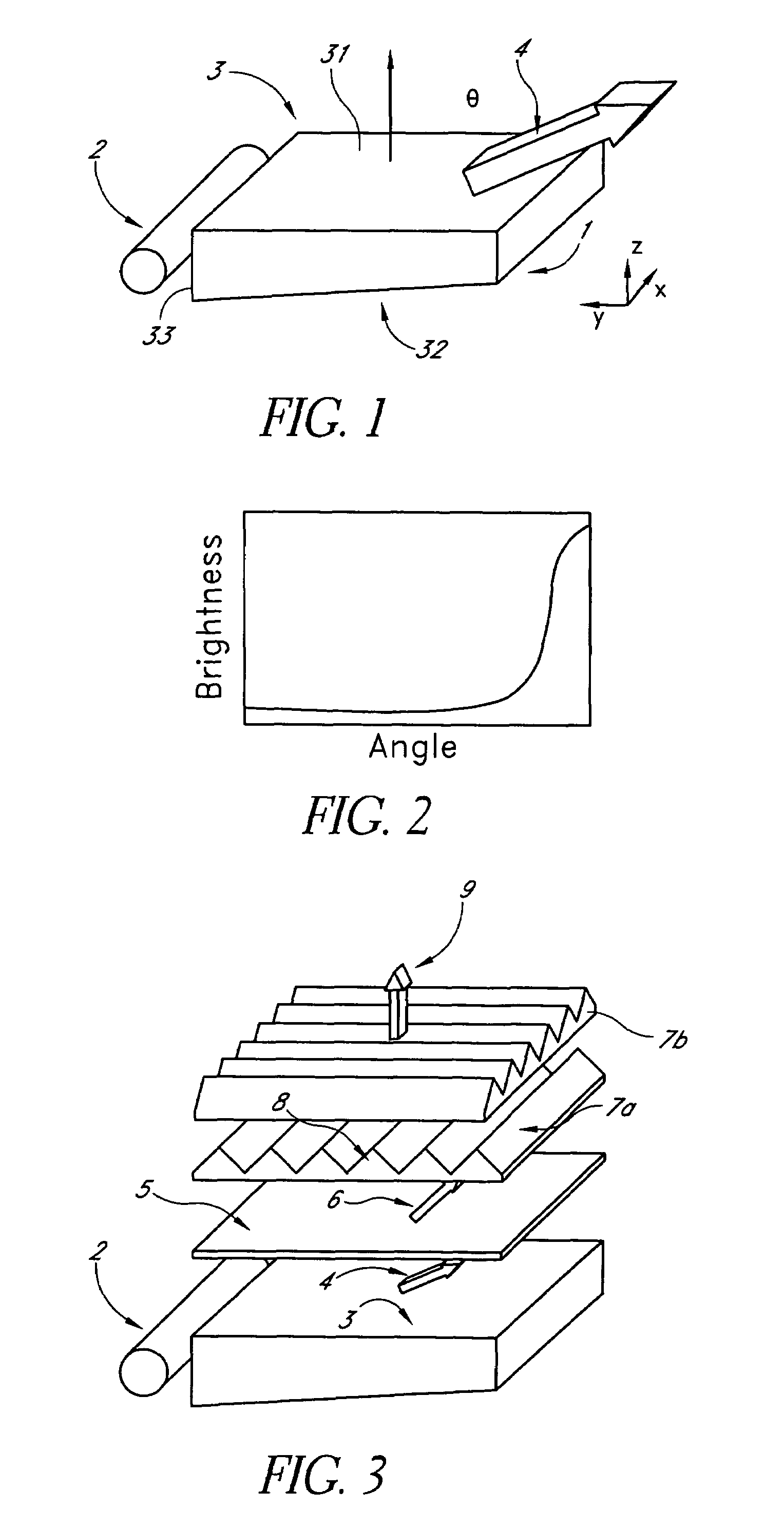
[0025]As described above, current flat panel displays include an edge-lit backlight to reduce the thickness of the displays. FIG. 1 shows an example edge-lit backlight unit 1, comprising a linear light source 2 and a light guide panel or plate 3 (LGP). This linear light source may comprise, for example, a cold cathode fluorescent tube (CCFL) lamp, an array (e.g., 2×2 array) of LED, an elongated tube LED, a fluorescent tube or any other suitable linear light source. This light source 2 is aligned parallel with an edge of the light guide plate 3 such that light from the linear light source 2 is incident on a side face 33 of the light guide plate 3. Although a linear light source is shown, in some embodiments, the light source is not linear.

[0026]The light guide panel 3 may comprise a substantially optically transmissive material capable of propagating light from the light source 2. The light guide panel 3 may comprise a plate having sides, each with a respective face, as well as a fro...


PUM


Abstract

A backlit light display comprises a light guide panel, a prismatic film, an asymmetric top diffuser and an LCD. A linear light source is disposed along a side face of the light guide panel. Light from the linear light source is transmitted though the light guide panel where it is spread and uniformly output through a front face to the prismatic film. Light incident on the prismatic film is redirected more along a first direction than along a second direction. This light is directed more normal to the LCD. An asymmetric diffuser is applied between the prismatic film and the LCD panel to smear the periodic information from the prismatic film and eliminate the Moiré fringe pattern resulting from interference between the periodic structure of the prismatic film and the periodic arrangement of pixels in the LCD. The asymmetric diffuser is aligned with respect to the prismatic film such that it scatters and spreads light more in a second direction than the first direction.

Description

PRIORITY APPLICATION[0001]This application claims the benefit of U.S. Provisional Patent Application No. 60 / 672,946, filed Apr. 20, 2005, the entire contents of which are hereby incorporated by reference herein.BACKGROUND[0002]1. Field of the Invention[0003]The present invention relates generally to backlit displays, such as liquid crystal displays (LCD) displays, and particularly to configurations of backlight displays using an asymmetric diffuser, such as an elliptical diffuser.[0004]2. Description of the Related Art[0005]For current flat panel displays such as LCD, edge-lit backlight panels are widely used to provide illumination. Such configurations reduce the thickness of the displays. An example backlight panel may comprise a plate made of optically transmissive material. A linear light source such as a fluorescent tube or a linear array of light emitting diodes (LED) may be disposed at an edge of the backlight panel to inject light into the panel. This light is guided within ...

Claims


Application Information

Patent Timeline
Patent Type & Authority Patents(United States)
IPC IPC(8): G02B6/10G02B6/00
CPCG02F1/133606G02B6/0053G02B6/0051G02B6/0046
Inventor QI, JUNPETERSEN, JOEL MIKAELRICH, CHRISTOPHER CHAPMAN
Owner WAVEFRONT TECH INC
Why Eureka
Try Eureka