All-optical delay generator for PPM communication systems based on a non-linear waveguide with a chirped DBR

a delay generator and non-linear waveguide technology, applied in electromagnetic transmission, electrical equipment, transmission, etc., can solve the problems of poor signal to noise ratio (snr), delay generators, however, suffer from non-linearity at high frequencies, and improve the design of delay generators. problems such as complicated problems

Active Publication Date: 2008-09-30
HRL LAB
View PDF24 Cites 1 Cited by
  • Summary
  • Abstract
  • Description
  • Claims
  • Application Information

AI Technical Summary

Problems solved by technology

This approach, however, suffers from a poor Signal to Noise Ratio (SNR).
Such delay generators, however, suffer from non-linearity at high frequencies, when changes in the transmitted waveform are faster than the round-trip time of an optical pulse in the devices.
This improved design of a delay generator, however, is rather complicated.
Moreover, one expects high optical losses in this device, since coupling between oppositely propagating optical

Method used


Image

  • All-optical delay generator for PPM communication systems based on a non-linear waveguide with a chirped DBR
  • All-optical delay generator for PPM communication systems based on a non-linear waveguide with a chirped DBR
  • All-optical delay generator for PPM communication systems based on a non-linear waveguide with a chirped DBR

Examples


Embodiment Construction

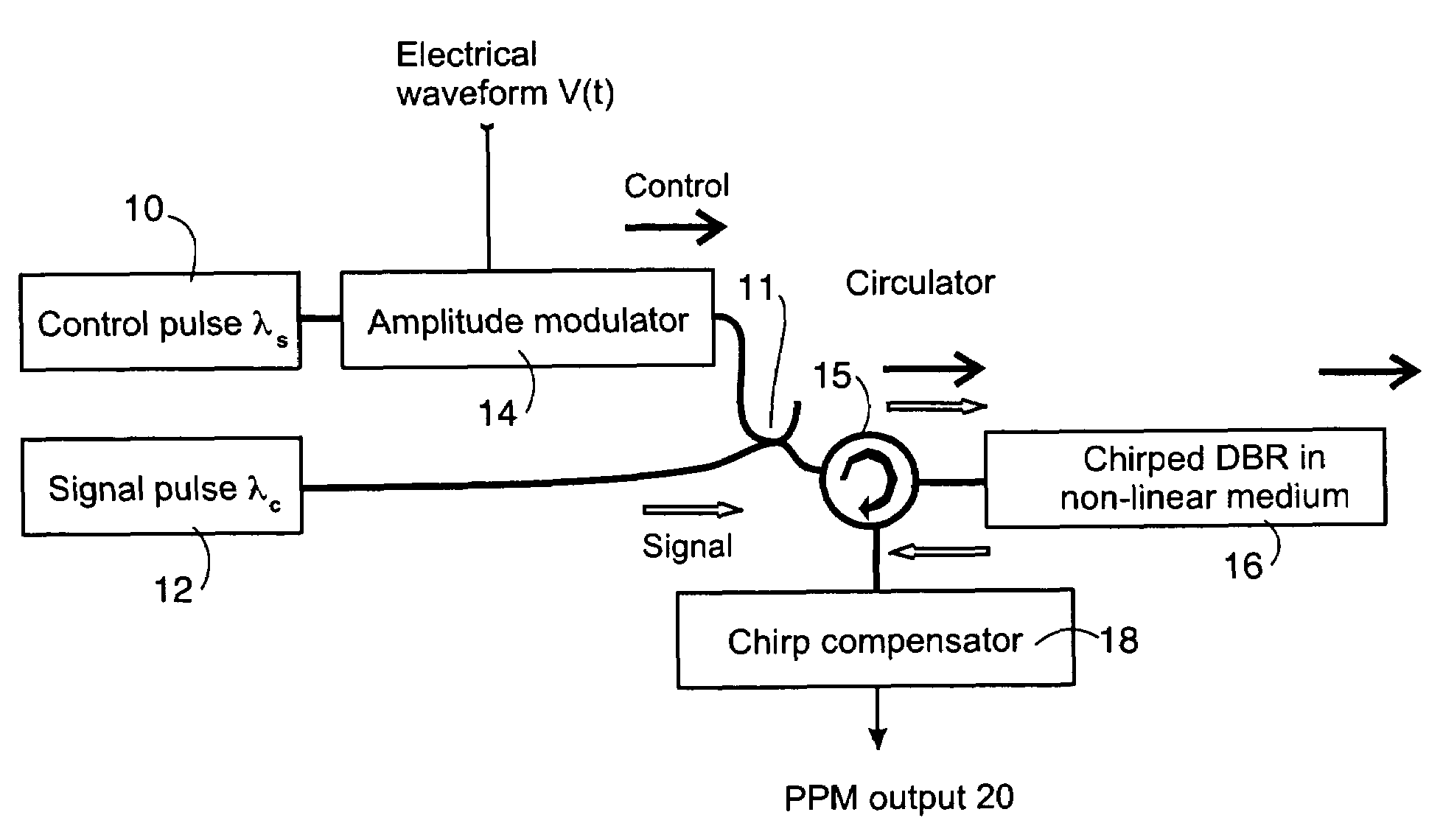
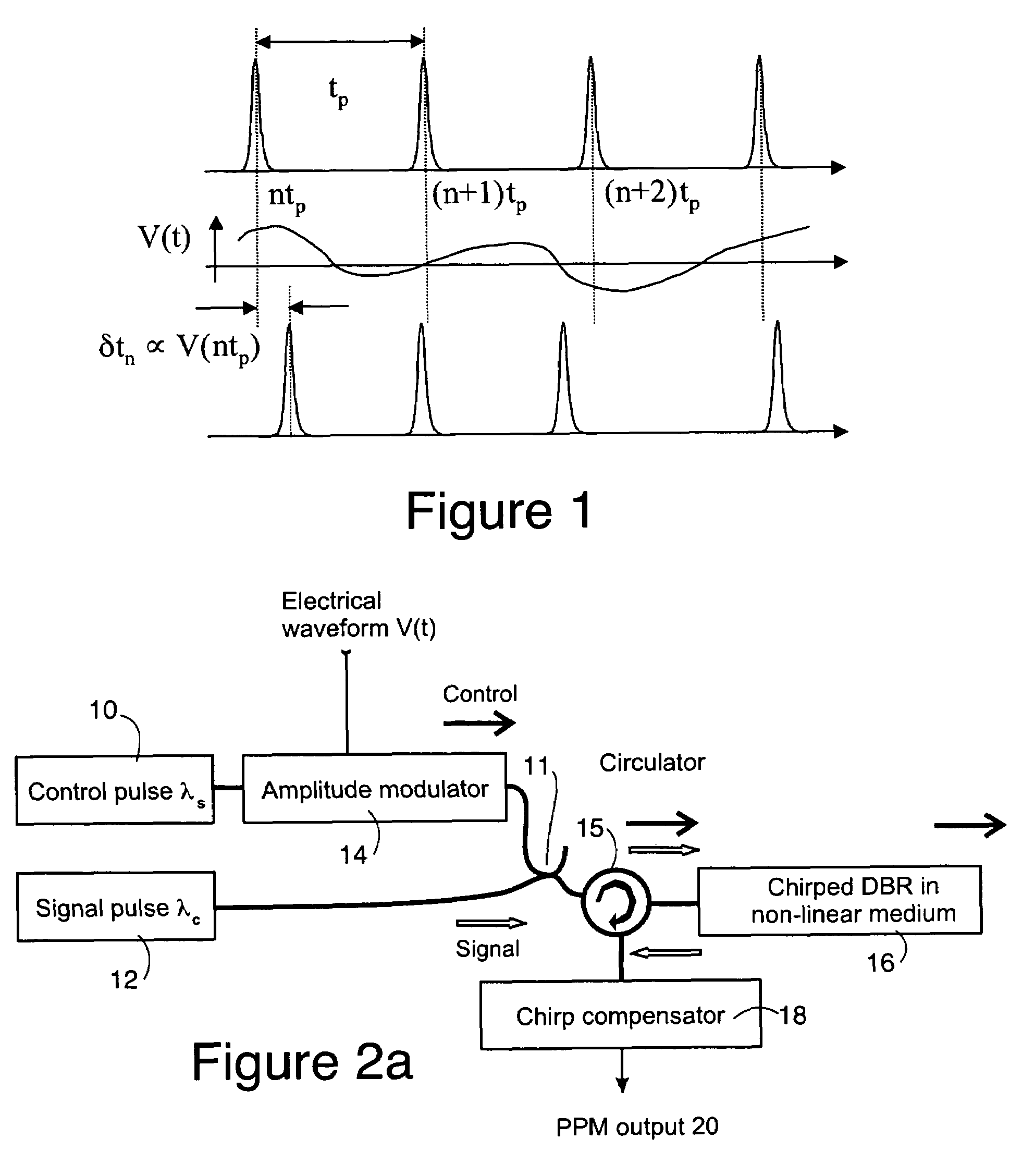
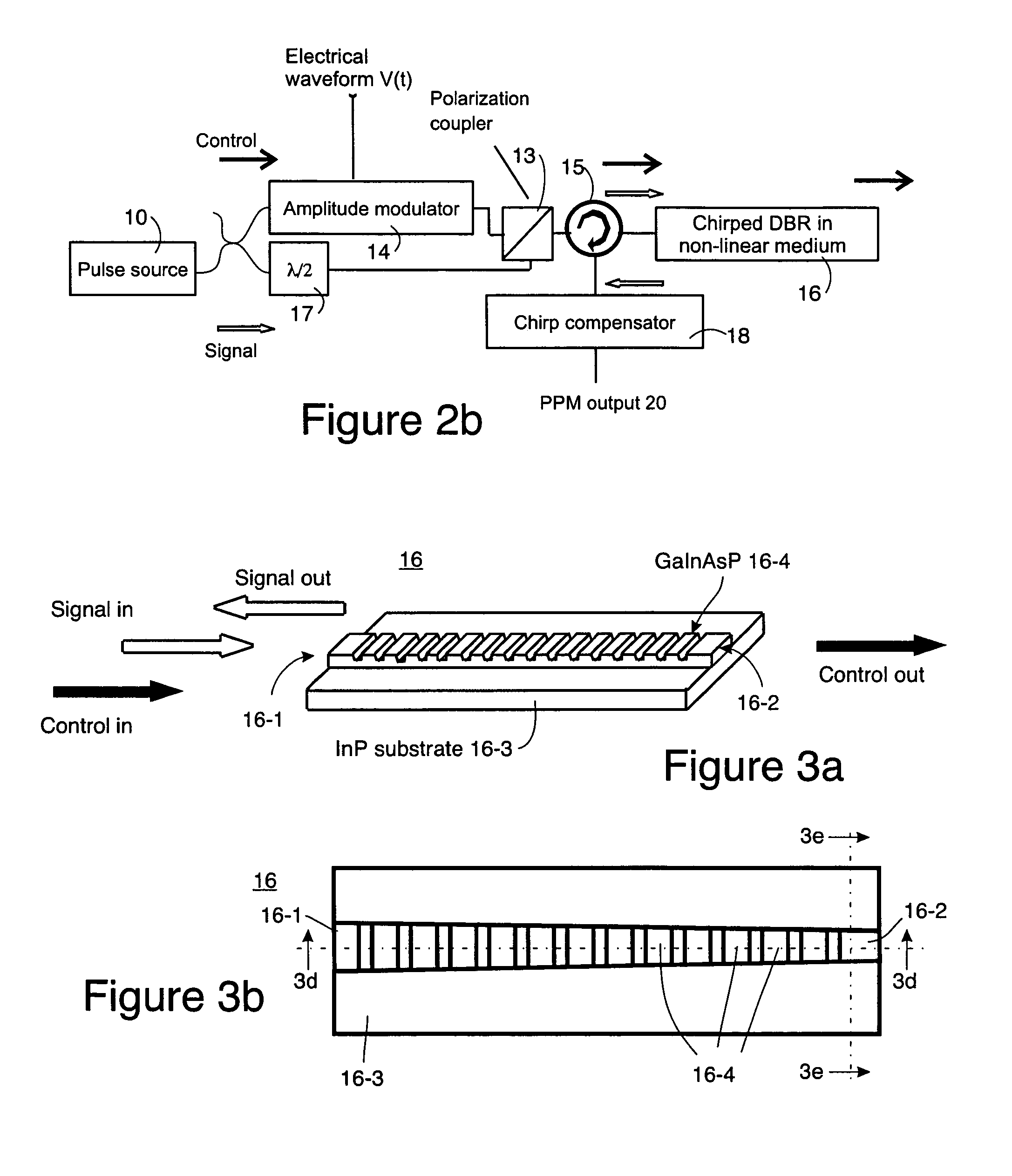
[0023]A block diagram of one embodiment of an all-optical PPM modulator is shown in FIG. 2a while another embodiment is shown by FIG. 2b. In the embodiment of FIG. 2a, equally-spaced signal and control optical pulses are generated by mode locked lasers 10 and 12. Suitable lasers for this application are manufactured by Pritel Inc. The lasers 10 and 12 produce synchronized outputs at slightly different optical wavelengths λs and λc, respectively. The amplitude of the control pulses is modulated in an EO modulator 14 (preferably a Mach-Zender LiNbO3 modulator) in proportion to an electrical waveform V(t), which is to be transmitted as PPM pulses 20. The control and signal pulses are combined in a sampler 11 and launched into a non-linear waveguide with a chirped distributed Bragg reflector (DBR) 16. The relative path length of the control and signal pulses is chosen to achieve temporal overlap of the two pulses in the waveguide 16.

[0024]Alternatively, in the embodiment of FIG. 2b the ...


PUM


Abstract

An all-optical PPM modulator comprises one or more sources of trains of optical control pulses and optical signal pulses, the optical control and optical signal pulses being equally spaced, but differentiated from one another by at least having different optical wavelengths and/or polarizations prior to modulation. An electro-optic modulator, for example, amplitude modulates the control pulses using a signal. A chirped Bragg reflector in an non-linear waveguide receives both the amplitude modulated optical control signal pulses and unmodulated optical signal pulses at an entrance port thereof, the waveguide having a path length selected to achieve temporal overlap of the control and signal pulses in the waveguide. The chirped Bragg reflector is resonant to the optical signal pulses and off-resonant to the optical control pulse. The signal pulses reflect the in chirped Bragg reflector and exit an entrance port thereof while the control pulses either are absorbed or exit an exit port of the chirped Bragg reflector.

Description

TECHNICAL FIELD[0001]This disclosure relates to an optically-controlled delay generator which may be used for a PPM modulator.BACKGROUND INFORMATION[0002]Many satellite and terrestrial optical communication systems require transmission of analog optical signals. A straightforward way to address this need is to modulate the amplitude (AM) of an optical carrier. This approach, however, suffers from a poor Signal to Noise Ratio (SNR). It is well known that broadband modulation schemes, which utilize higher bandwidth than that of the transmitted waveform, may improve the SNR over that achieved with AM. Pulse position modulation (PPM) is one of such techniques. In PPM, a shift in the pulse position represents a sample of the transmitted waveform, as shown in FIG. 1. It can be shown that for a given power, SNRPPM∝SNRAM(tp / τ)2, where tp is the spacing between un-modulated pulses and τ—the pulse duration, respectively. See H. S. Black, Modulation Theory, D. Van Nostrand (1953).[0003]The imp...

Claims


Application Information

Patent Timeline
IPC IPC(8): H04B10/04H04B10/12
CPCH04B10/508
Inventor IONOV, STANISLAV I.
Owner HRL LAB
Why Eureka
Try Eureka