
Network monitoring method and apparatus

a network monitoring and network monitoring technology, applied in the field of network monitoring techniques, can solve the problems of increasing the load of the monitoring network, the inability to update the monitoring network, and the increase of the number of transmission devices

Inactive Publication Date: 2008-09-30
FUJITSU LTD
View PDF5 Cites 32 Cited by
  • Summary
  • Abstract
  • Description
  • Claims
  • Application Information

AI Technical Summary

Benefits of technology

[0012]It is a general object of the present invention to provided a network monitoring method and apparatus in which the above-mentioned problems are eliminated.
[0013]A more specific object of the present invention is to provide a network monitoring method and system which reduces a load to a monitoring network without deteriorating accuracy of detecting a malfunction.
[0021]According to the above-mentioned present invention, a load to a monitoring network can be reduced without deteriorating accuracy of malfunction detection even if a number of network constituent elements, which constitute a communication network, is increased.

Problems solved by technology

However, such a notification is not made in cases of a communication disconnection of the monitoring network 14, a power supply disconnection of a transmission apparatus, a malfunction of a trap sending part, etc.
On the other hand, there are many cases in which a monitoring network is not updated even if a number of monitoring and transmission apparatuses is increased since it takes an extremely large cost to update the monitoring network as an infrastructure.
In such a case, in order to detect immediately an occurrence of a malfunction and recovery thereof, it is necessary to perform a health check or polling at a short period, which increases a load to a monitoring network with an increase in a number of transmission apparatuses.

Method used


Image

  • Network monitoring method and apparatus
  • Network monitoring method and apparatus
  • Network monitoring method and apparatus

Examples


second embodiment

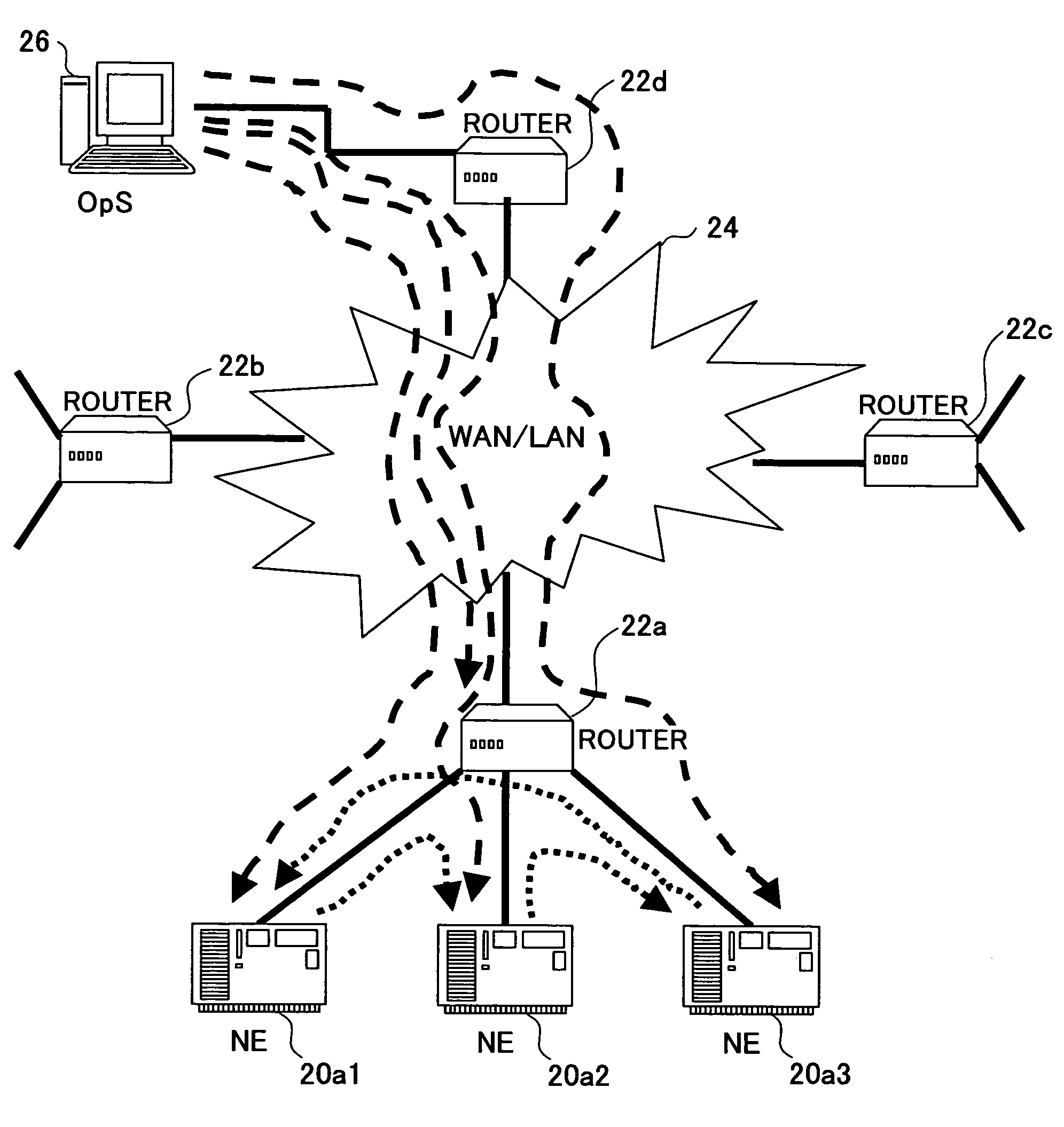
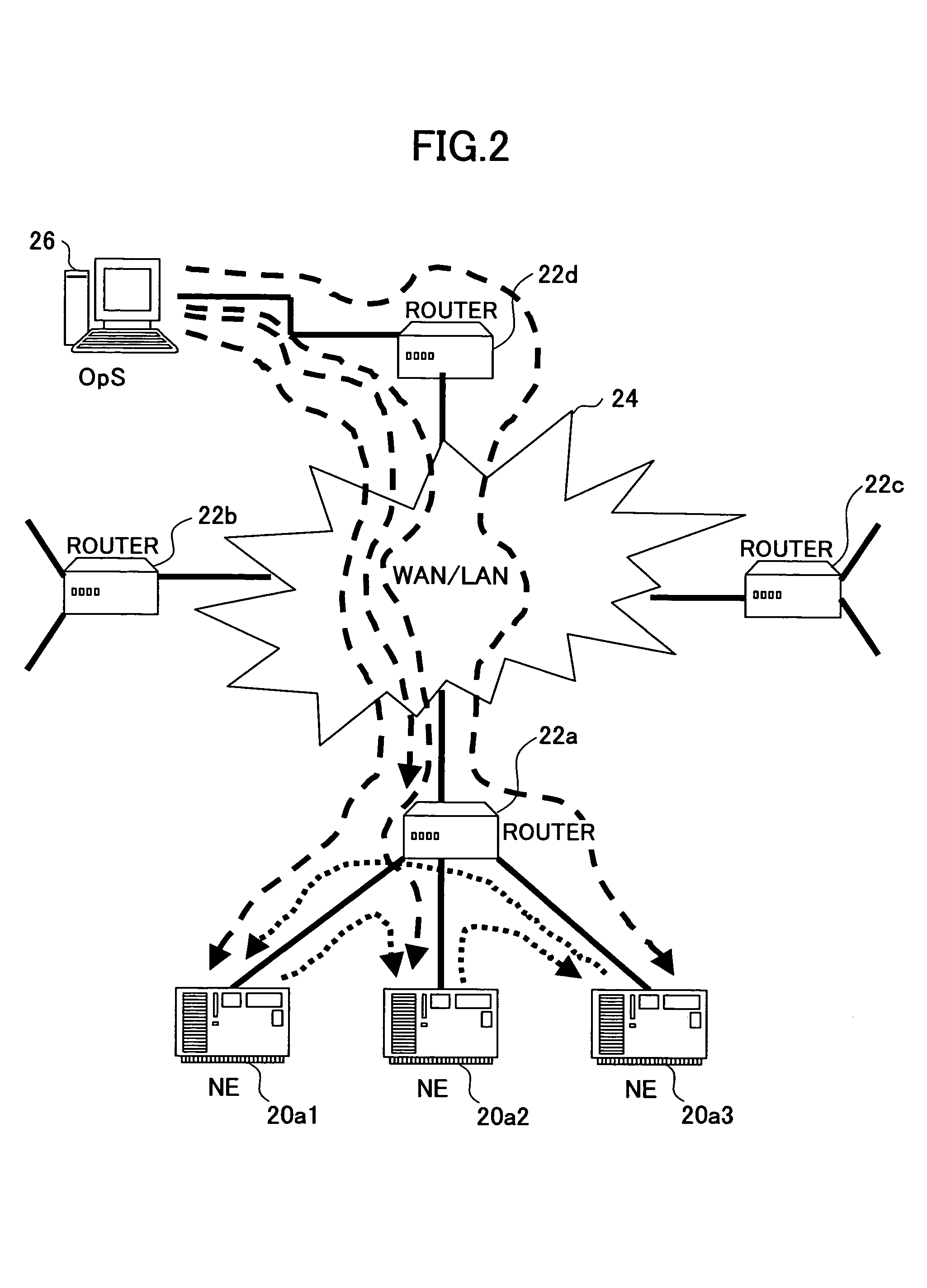
[0075]FIG. 12 is an illustration for explaining the present invention. FIG. 13 is a flowchart of a process performed by the health check function 32. FIG. 14 is a flowchart of a process performed by the alarm and performance collection function 33.

[0076]In FIG. 13, the health check function 32 of the operation system 26 determines, in step S21, whether or not a result of the health check indicates abnormality. If it is determined that the result of the health check indicates abnormality, the process proceeds to step S22 where the health check function 32 updates the malfunction information of the malfunction information management database 37 by changing from “NO” to “YES”.

[0077]Then, in step S23, the health check function 32 issues a status change request to the monitored NE management function 35. The monitored NE management function 35 acquires, in step S24, information from the malfunction information management database 37. Then, the monitored NE management function 35 updates,...

third embodiment

[0084]FIG. 15 is an illustration for explaining the present invention. FIG. 16 is a flowchart of a process performed by the health check function 32. FIG. 17 is a flowchart of a process performed by the alarm and performance information collection function 33. Additionally, FIG. 18 is a flowchart of a process performed by the health check function 44. FIG. 19 is flowchart of a process performed by the trap management function 34. FIG. 20 is a flowchart of a process performed by the trap transmitting function 43.

[0085]In FIG. 16, the health check function 32 of the operation system 26 determines, in step S41, whether or not a result of a health check indicates abnormality. If the result of the health check indicates abnormality, the process proceeds to step S42 where the health check function 32 updates the malfunction information of the malfunction information management database 37 by changing from “NO” to a “YES”. Then, the health check function 32 issues, in step S43, a status ch...

fourth embodiment

[0100]FIG. 21 is an illustration for explaining the present invention. FIGS. 22 and 23 are flowcharts of parts of a process performed by the trap management function 34. FIG. 24 is a flowchart of a process performed by the OsP request analysis function 42.

[0101]In FIG. 22, upon receipt of the SNMP trap, the trap management function 34 of the operation system 26 executes a trap stop request on the transmission apparatus, which sent the SNMP trap in step S91. The trap management function 34 updates, in step S92, the malfunction information in the malfunction information management database 37 by changing to “YES” or “NO” according to the contents of the received SNMP trap. The trap management function 34 issues, in step S93, a status change request to the monitored NE management function 35. The monitored NE management function 35 acquires, in step S94, information from the malfunction information management database 37. Then, in step S95, the monitored NE management function 35 updat...


PUM


Abstract

A network monitoring method and system reduces a load to a monitoring network without deteriorating accuracy of detecting a malfunction. A plurality of network constituent elements that constitute a communication network are connected to an operation system through a monitoring network. A health check for detecting a malfunction is periodically performed between a group of the network constituent elements positioned closed to each other within the communication network at a short monitoring period. A health check of malfunction detection on all of the network constituent elements is performed by the operation system at a long monitoring period longer than the short monitoring period.

Description

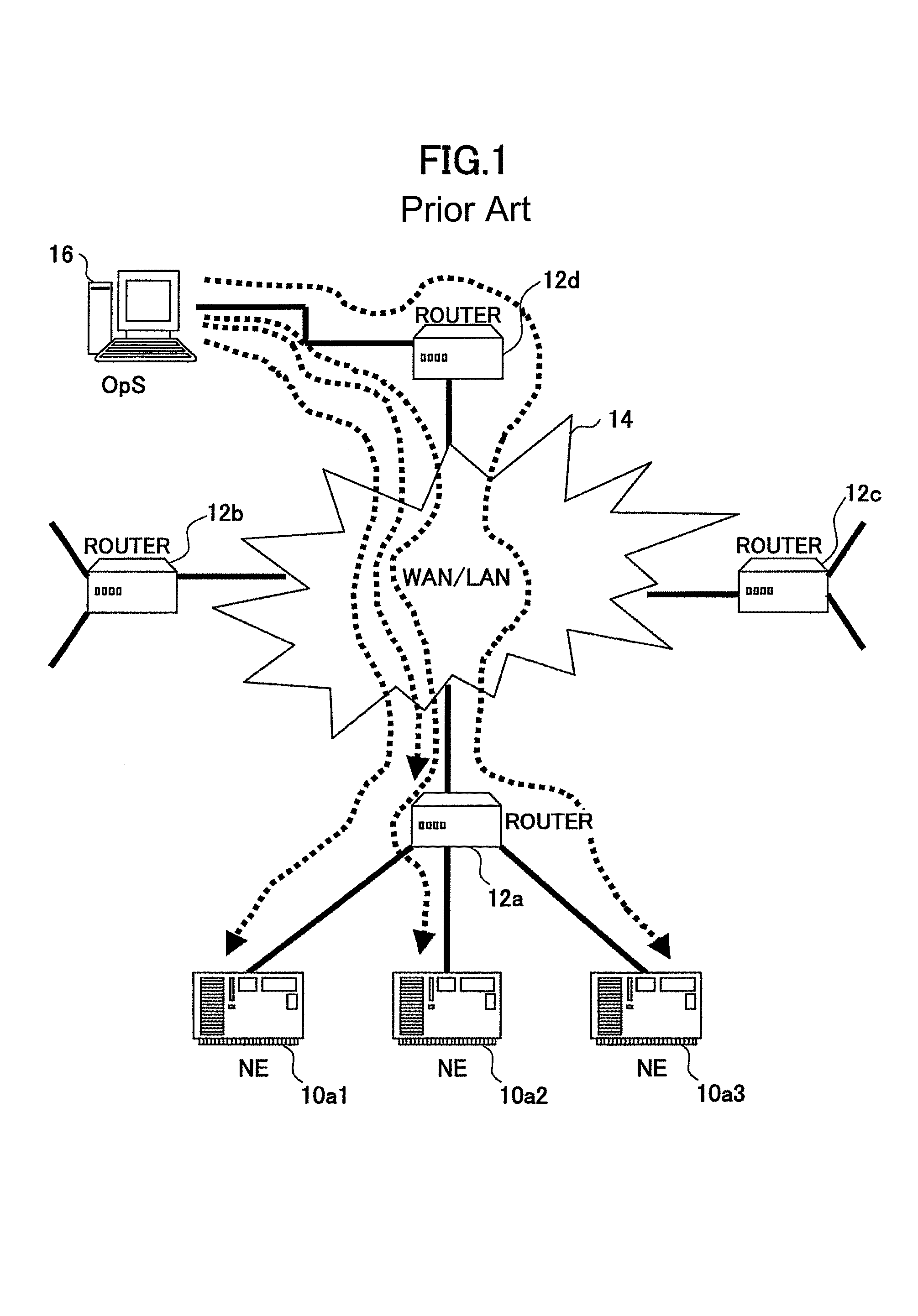
BACKGROUND OF THE INVENTION[0001]1. Field of the Invention[0002]The present invention generally relates to a network monitoring technique and, more particularly, to a network monitoring method for monitoring and controlling network constituent elements, such as a transmission apparatus and a router, using an operation system, and a network monitoring apparatus performing such a network monitoring method.[0003]2. Description of the Related Art[0004]Conventionally, network structural elements such as a transmission apparatus and a router that constitute a communication network are monitored and controlled by an operation system.[0005]FIG. 1 is an illustration for explaining an example of a conventional network monitoring method. In FIG. 1, transmission apparatuses 10a1, 10a2 and 10a3 and routers 12a, 12b and 12c, each of which is a network constituent element, constitute a communication network. The routers 12a, 12b and 12c are connected to a monitoring network 14 such as a WAN or LAN...

Claims


Application Information

Patent Timeline
Patent Type & Authority Patents(United States)
IPC IPC(8): G06F11/00H04L12/70G06F11/30
CPCH04L43/0817H04L41/0893H04L41/06H04L41/0213
Inventor MATSUNO, AKINORITAKEDA, MASAYUKIHASEGAWA, MASAYUKIKITAGAWA, HIROFUMIHANDA, TOSHIMITSU
Owner FUJITSU LTD
Learn More