Multimode hybrid energy railway vehicle system and method

a hybrid energy and railway vehicle technology, applied in the field of vehicle systems and methods, can solve the problems of unsatisfactory attempts to make productive use of such energy, prior art locomotives typically waste the energy generated from dynamic braking, and electric energy generated in the dynamic braking mode is typically wasted

Inactive Publication Date: 2008-10-07
GE GLOBAL SOURCING LLC
View PDF67 Cites 70 Cited by
  • Summary
  • Abstract
  • Description
  • Claims
  • Application Information

AI Technical Summary

Problems solved by technology

In other words, electric energy generated in the dynamic braking mode is typically wasted.
As indicated above, prior art locomotives typically waste the energy generated from dynamic braking.
Attempts to make productive use of such energy have been unsatisfactory.
Such systems are not suited for recovering energy to propel the locomotive itself.
Among the disadvantages of such a system are the safe storage of the hydrogen gas and the need to carry water for the electrolysis process.
Still other prior art systems fail to recapture the dynamic braking energy at all, but rather selectively engage a special generator that operates when the associated vehicle travels downhill.
One of the reasons such a system is unsatisfactory is because it fails to recapture existing braking energy.
Such prior art hybrid energy railway vehicles fail to recapture dynamic braking energy generated by the traction motor of the hybrid energy railway vehicle and is required to turn on and off the turbine engine and generator as required by the level of charge of the hybrid energy railway vehicle storage system.

Method used


Image

  • Multimode hybrid energy railway vehicle system and method
  • Multimode hybrid energy railway vehicle system and method
  • Multimode hybrid energy railway vehicle system and method

Examples


Embodiment Construction

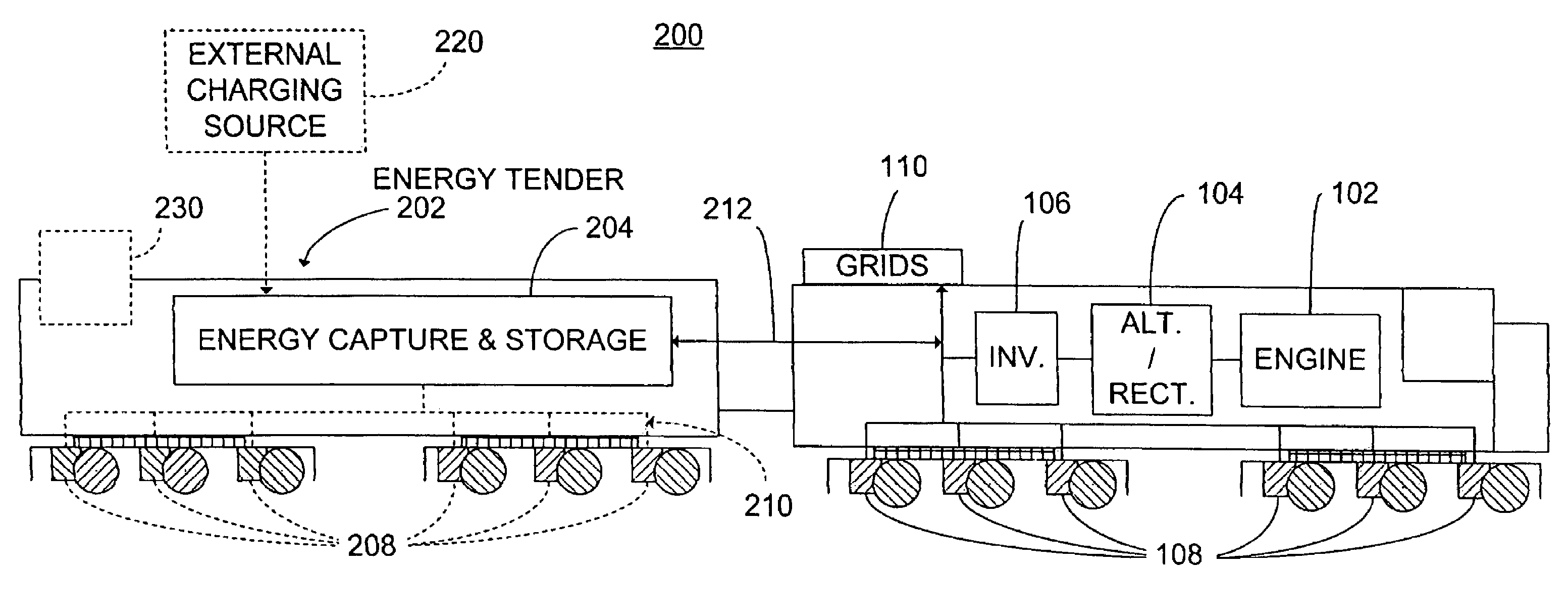
[0040]FIG. 2 is a block diagram of one embodiment of a hybrid energy locomotive system 200. In this embodiment, the hybrid energy locomotive system 200 preferably includes an energy tender vehicle 202 for capturing and regenerating at least a portion of the dynamic braking electric energy generated when the locomotive traction motors operate in a dynamic braking mode. The energy tender vehicle 202 is constructed and arranged to be coupled to the locomotive in a consist configuration, and includes an energy capture and storage system 204 (sometimes referred to as an energy storage medium or an energy storage). It should be understood that it is common to use two or more locomotives in a consist configuration and that FIG. 2 illustrates a single locomotive for convenience.

[0041]In one embodiment, the energy capture and storage system 204 selectively receives electrical power generated during the dynamic braking mode of operation and stores it for later regeneration and use. In the alt...


PUM


Abstract

A hybrid energy railway vehicle system having a traction motor with a dynamic braking mode of operation for dynamically braking the traction motor and for generating dynamic braking electrical energy and an electrical energy storage system that is in electrical communication with the traction motor and that stores dynamic braking electrical energy generated by the traction motor. The system also has a hybrid energy railway vehicle with a plurality of wheels wherein the traction motor has a motoring mode of operation for driving one of the wheels in response to electrical input energy. A converter selectively provides stored electrical energy from the energy storage system to the traction motor as electrical input energy for driving one or more of wheels. The hybrid energy railway vehicle is optionally equipped computer readable medium having computer executable instructions for controlling the operation of the hybrid energy railway vehicle and a processor configured to control the operation of the railway vehicle as a function of at least one of a plurality of operating modes.

Description

CROSS REFERENCE TO RELATED APPLICATIONS[0001]The invention of the present application is a continuation-in-part of The invention of the present application is a continuation-in-part of U.S. patent application Ser. No. 10 / 435,261, filed on May 9, 2003, MULTIMODE HYBRID ENERGY RAILWAY VEHICLE SYSTEM AND METHOD, which claims priority from U.S. patent application Ser. No. 10 / 032,714, filed on Dec. 26, 2001, entitled LOCOMOTIVE ENERGY TENDER, and from U.S. Provisional Application Ser. No. 60 / 278,975, filed on Mar. 27, 2001, the entire disclosure of which are incorporated herein by reference.FIELD OF THE INVENTION[0002]The invention relates generally to vehicle systems and methods for use in connection with railways. In particular, the invention relates to a railway vehicle system operable from stored electrical energy, such as stored electrical energy being produced by a charging generator and by dynamic braking energy generated by electric traction motors during dynamic braking, the veh...

Claims


Application Information

Patent Timeline
Patent Type & Authority Patents(United States)
IPC IPC(8): B61C3/00B60L7/22B60L15/20B60L50/15B60L50/30
CPCB60L7/06B60L7/14B60L7/22B60L9/005B60L9/02B60L9/16B60L11/005B60L11/12B60L11/123B60L11/14B60L11/16B60L11/1803B60L15/20B60L15/2045B61C3/02B60L7/12B60L2200/26B60L2220/20B60L2260/28Y02T10/6217Y02T10/7005Y02T10/7022Y02T10/7283Y02T30/12Y02T90/16B60L50/40B60L50/15B60L50/61B60L50/16B60L50/30B60L50/51Y02T10/62Y02T10/70Y02T10/72Y02T30/00
Inventor KUMAR, AJITH KUTTANNAIR
Owner GE GLOBAL SOURCING LLC
Why Eureka
Try Eureka