
Universal memory card connector

a memory card and connector technology, applied in the field of memory card connectors, can solve the problems of reducing the service life of the metal conducting terminal, increasing the cost, and curved or damaged metal conducting terminals, so as to prevent biasing, prevent damage, and be easily and quickly assembled

Inactive Publication Date: 2008-10-07
CHANT SINCERE
View PDF8 Cites 15 Cited by
  • Summary
  • Abstract
  • Description
  • Claims
  • Application Information

AI Technical Summary

Benefits of technology

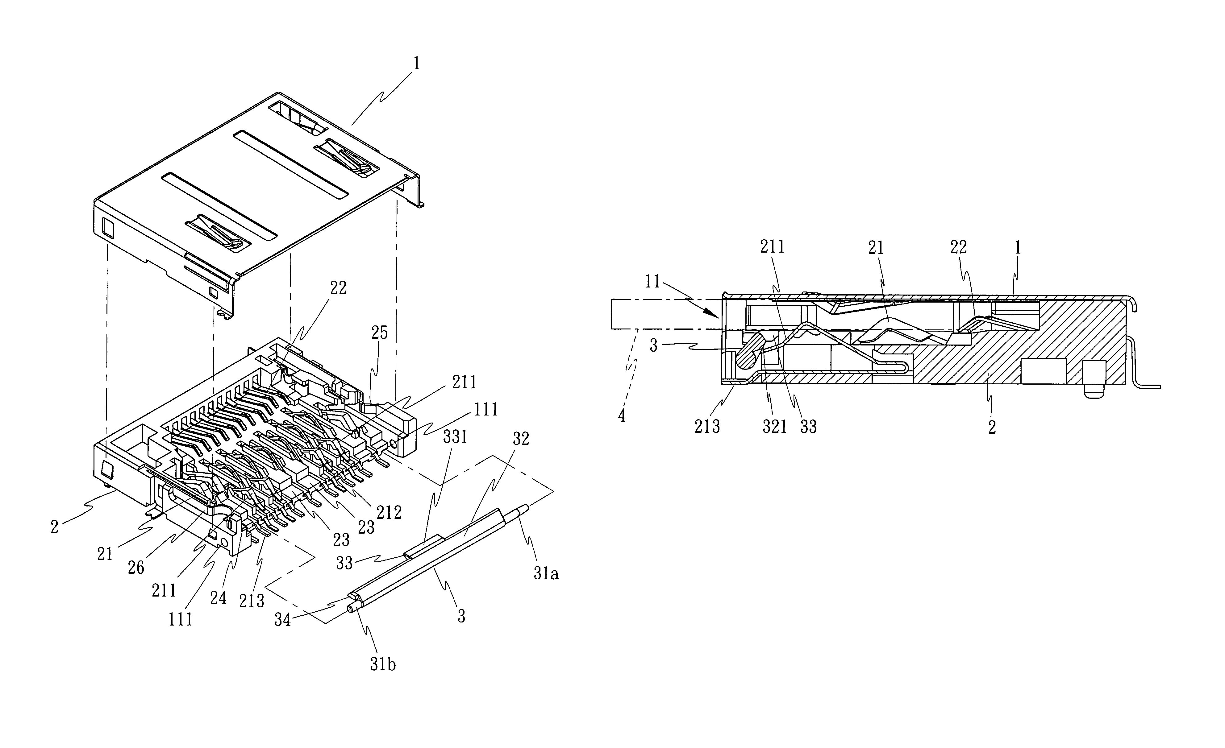
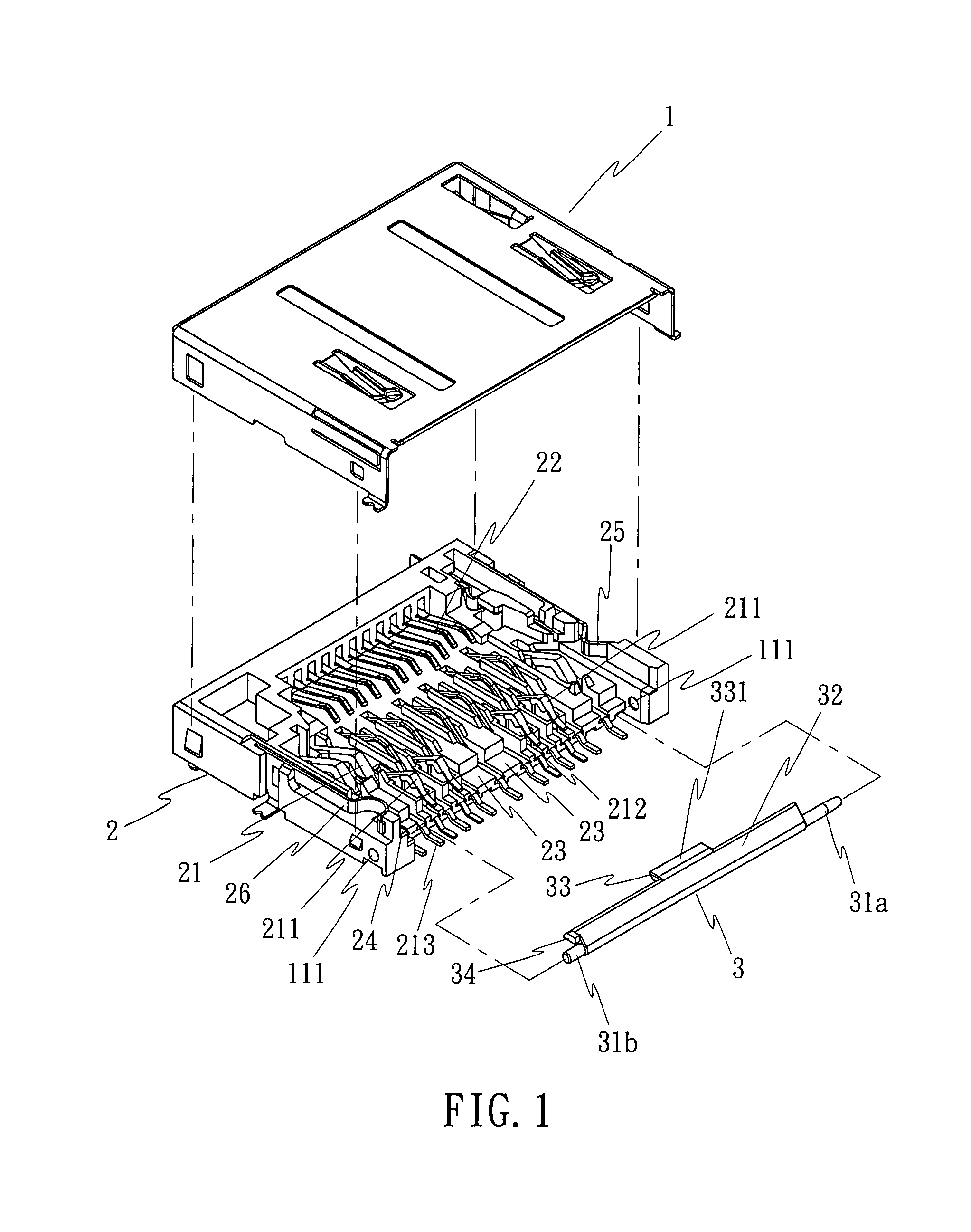
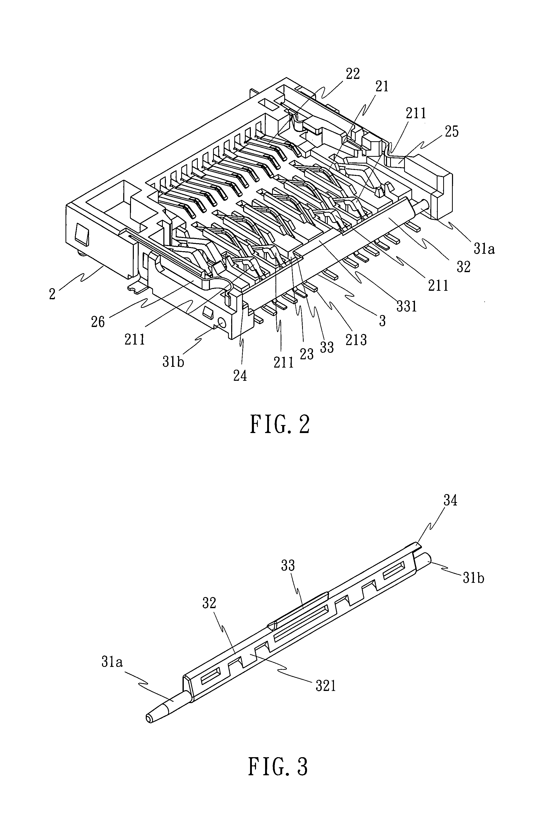
[0007]The present invention has been accomplished under the circumstances in view. According to one aspect of the present invention, the memory card connector comprises a pivot shaft member pivotally disposed in the front side of the insertion hole for memory card. The pivot shaft member has a protruding portion, and a guide block extending from the protruding portion. The guide block has a horizontally extending guide surface. When inserting a thin type memory card into the insertion hole, the guide surface guides the memory card into the insertion hole in horizontal, preventing biasing. When inserting a thick memory card into the insertion hole, the memory card will touch the protruding portion, causing the pivot shaft member to rotate through an angle, and the inner part of the protruding portion will be forced downwards against the front row of terminals to prevent damage. When ejecting the inserted memory card, the front row of terminals imparts a spring force to the pivot shaft member, rotating the pivot shaft member in the reversed direction to its former position. Because the invention uses a small number of parts, the memory card connector can easily and quickly be assembled. Further, the simple structural design greatly reduces the cost of the memory card connector.

Problems solved by technology

When inserting a thin type memory card (for example, mini SD memory card) into the common insertion hole, the thin type memory card may be tilted or biased toward the left or right side and forced to hit the row of metal conducting terminals at the front side of the terminal holder block, causing the metal conducting terminals to be curved or damaged.
This design is functional, however it uses a number of parts, complicating the installation and increasing the cost.

Method used


Image

  • Universal memory card connector
  • Universal memory card connector
  • Universal memory card connector

Examples


Embodiment Construction

[0023]Referring to FIGS. 1˜10, a universal memory card connector in accordance with a first embodiment of the present invention is shown comprised of a top cover 1, an electrically insulative terminal holder block 2, and a pivot shaft member 3.

[0024]The top cover 1, as shown in FIG. 1, is a metal cover plate fitting over the terminal holder 1 to form with the terminal holder 1 the body of the memory card connector that defines an insertion hole 11 at one side for the insertion of any of a variety of memory cards, for example, a thin type memory card (such as mini SD memory card) 4, or a thick memory card (such as SD memory card) 5.

[0025]The terminal holder block 2, as shown in FIGS. 1 and 2, is an electrically insulative member holding multiple sets of terminals 21, 22 for the connection of different memory cards selectively. Because the arrangement and composition of the sets of terminals 21, 22 are of the known art and not within the scope of the claims of the present invention, n...


PUM


Abstract

In a memory card connector, a pivot shaft member is pivotally provided in a front side of the insertion hole for memory card for controlling the gap of the insertion hole for the insertion of a different memory card. The pivot shaft member has a protruding portion protruded from the periphery, and a guide block extending from the protruding portion for guiding the insertion of a thin type memory card into the insertion hole in horizontal. Insertion of a thick memory card into the insertion hole forces the protruding portion to rotate the pivot shaft and to hold down the front row of terminals in the memory card connector, preventing deformation or damage of the terminals due to improper insertion of the memory card into the insertion hole.

Description

BACKGROUND OF THE INVENTION[0001](a) Field of the Invention[0002]The present invention relates to a memory card connector and more particularly, to a universal memory card connector, which has a pivot shaft member pivotally provided in the front side of the insertion hole for memory card and rotatable between two positions to control the gap of the insertion hole for the insertion a different type of memory card.[0003](b) Description of the Prior Art[0004]Various different types of memory cards, such as SD memory card, MMC and MMC4.0 memory card, MS memory card, XD memory card, SM memory card, mini SD memory card, RS-MMC memory card, RS-MMC4 memory card, and etc are commercially available. These memory cards have different sizes. Therefore, universal memory card connectors are developed for receiving any of a variety of memory cards.[0005]A conventional universal memory card connector is known comprising a metal top cover, a terminal holder block, and multiple metal conducting termi...

Claims


Application Information

Patent Timeline
Patent Type & Authority Patents(United States)
IPC IPC(8): H01R13/44
CPCG06K7/0021H01R27/00H01R13/4536H01R13/703
Inventor YEN, MING HUILAI, CHUN MING
Owner CHANT SINCERE
Learn More