Inter-vehicle distance detecting device and inter-vehicle distance detecting method

a technology of inter-vehicle distance and detection device, which is applied in the direction of measurement device, scene recognition, instruments, etc., can solve the problems of reduced received signal strength, decreased measurement distance precision, and inferior measurement distance precision, so as to achieve precise measurement distance

Inactive Publication Date: 2008-10-07
ALPINE ELECTRONICS INC
View PDF6 Cites 43 Cited by
  • Summary
  • Abstract
  • Description
  • Claims
  • Application Information

AI Technical Summary

Benefits of technology

[0010]The present invention is devised in view of the foregoing problems, and has an object to precisely measure an inter-vehicle distance from a user's own vehicle to a neighboring vehicle even if the neighboring vehicle cannot be detected by a radar due to the influence of multipath and the like.
[0012]According to the present invention configured as described above, since both the distance acquired by the radar and the visual angle of the neighboring vehicle acquired by the image taken by the camera are highly precise, it is possible to precisely calculate the width of the neighboring vehicle based on these pieces of information if the radar is detecting the neighboring vehicle. If the radar becomes unable to detect the neighboring vehicle, since the distance to the neighboring vehicle is calculated based on the precise width information for the neighboring vehicle stored in the recording medium and the precise visual angle of the neighboring vehicle acquired by the image taken by the camera at this time, the measured distance is precise.
[0013]In this way, according to the present invention, the inter-vehicle distance from the user's own vehicle to the neighboring vehicle is precisely measured by the radar if the radar is detecting the neighboring vehicle, and the inter-vehicle distance can be precisely measured based on the precise vehicle width already stored and the precise vehicle visual angle acquired by the image recognition process even if the radar becomes unable to detect the neighboring vehicle.

Problems solved by technology

However, a neighboring vehicle might not be detected due to the influence of multipath where a direct wave, which is reflected by the neighboring vehicle and directly returns to the radar, and an indirect wave, which is further reflected by a road surface or the like and indirectly returns to the radar, cancel out each other, resulting in the reduction of a received signal strength.
On the other hand, according to the method which uses cameras, though the precision of the measured distance is inferior to that measured by the radar, the above-described multipath phenomenon where a neighboring vehicle cannot be detected will not occur.
However, there arises a problem that the precision of the measured distance decreases if the radar cannot detect the neighboring vehicle and the radar is simply switched over to the cameras.
However, the technology disclosed by Japanese Unexamined Patent Publication No.
H6-230115 only calculates the reliability of the distance measured by the cameras, and cannot increase the precision of the measured distance.

Method used


Image

  • Inter-vehicle distance detecting device and inter-vehicle distance detecting method
  • Inter-vehicle distance detecting device and inter-vehicle distance detecting method
  • Inter-vehicle distance detecting device and inter-vehicle distance detecting method

Examples


first embodiment

[0019]A description will now be given of a first embodiment of the present invention with reference to drawings.

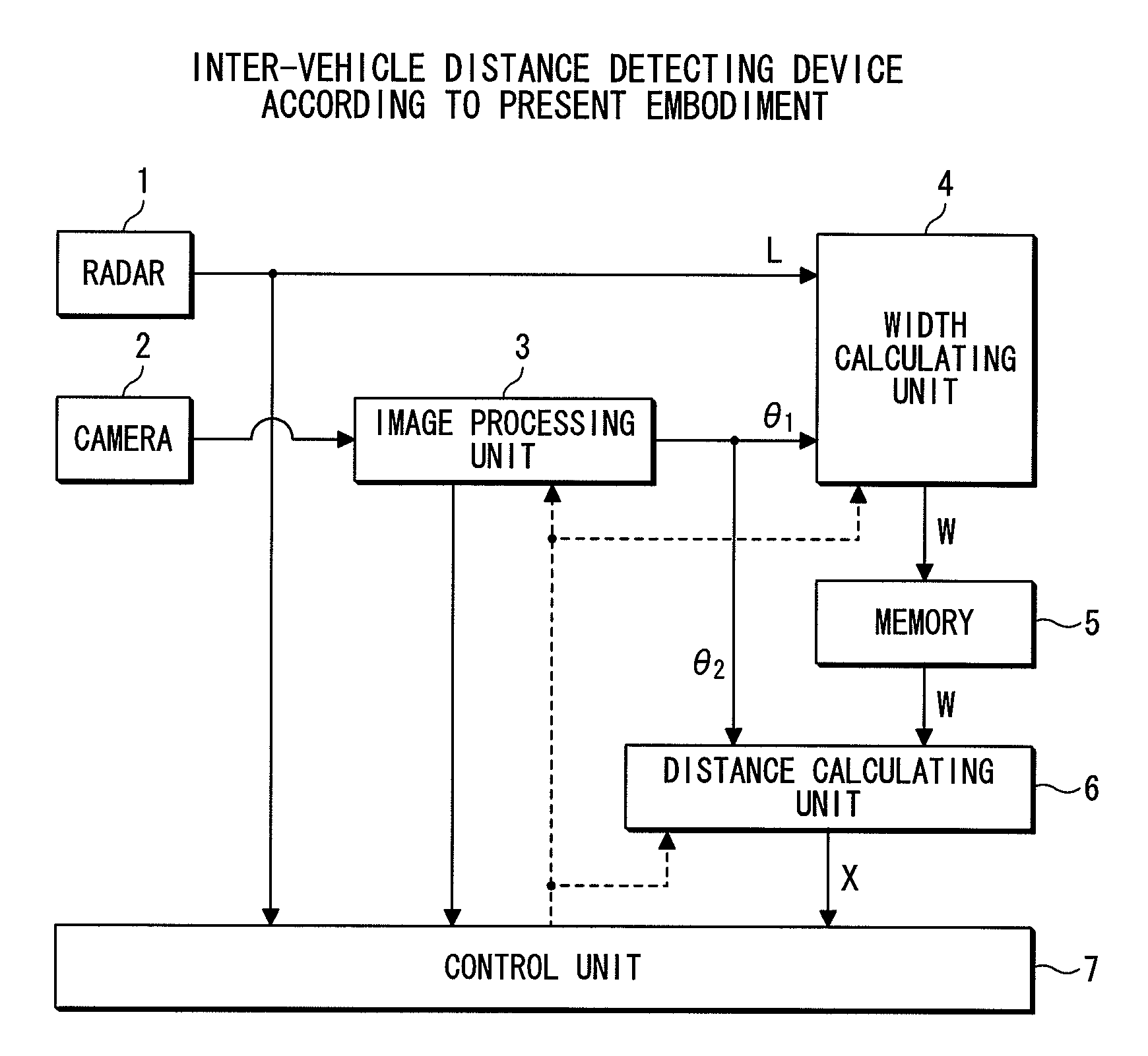
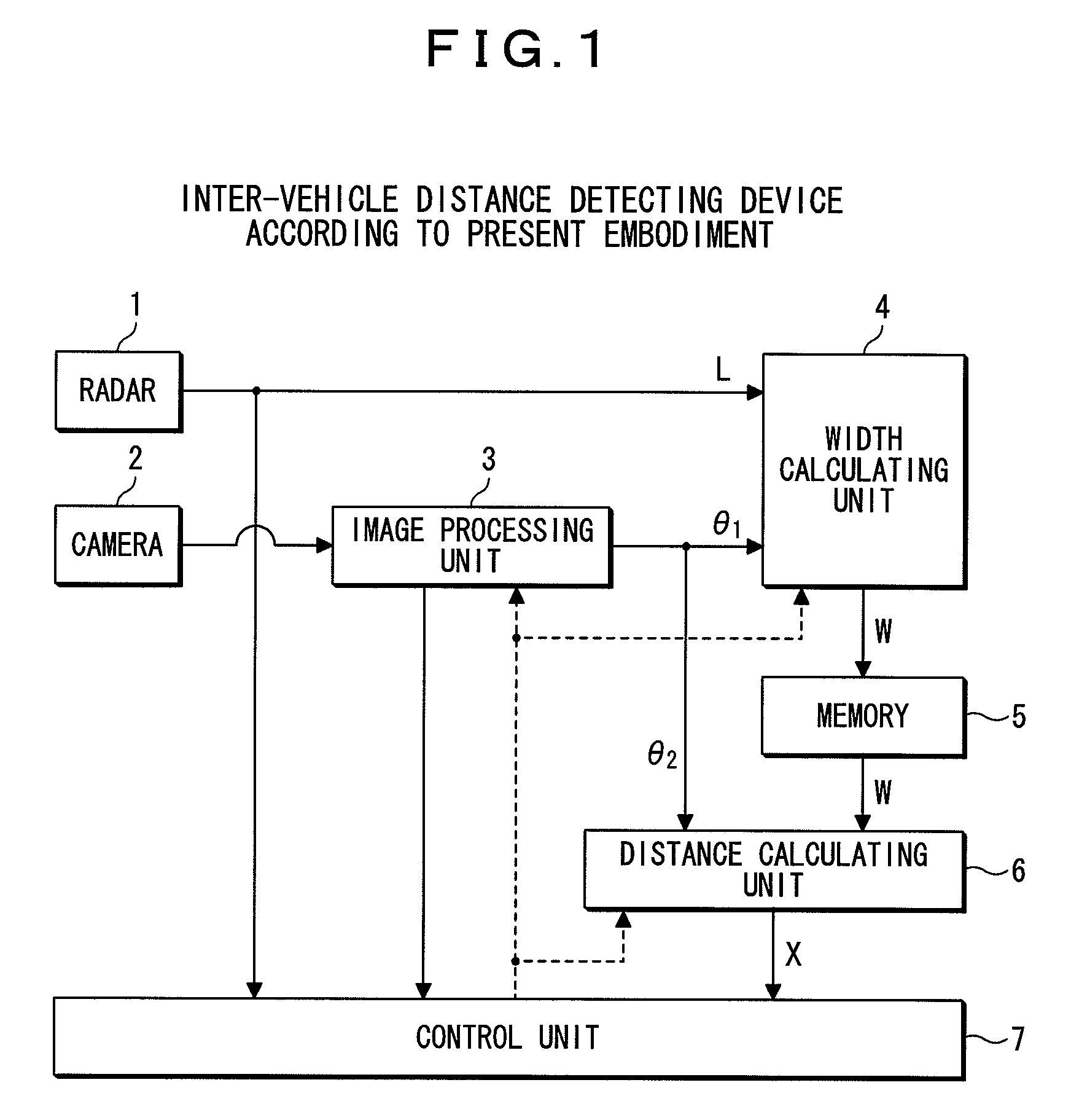
[0020]In FIG. 1, reference numeral 1 denotes a radar, and is installed at the rear of a vehicle. This radar 1 emits a radio wave such as a millimeter wave to the rear of the vehicle and receives the millimeter wave reflected from behind, thereby measuring the position (distance from and direction with respect to the user's own vehicle) and a relative velocity of a neighboring vehicle present behind the user's own vehicle. The distance from the user's own vehicle to the neighboring vehicle (inter-vehicle distance) is measured based on the time of travel of the millimeter wave from emission to reception after the reflection by the neighboring vehicle, and the velocity of the millimeter wave. It should be noted that in addition to a millimeter wave radar, an infrared radar and other radars may be used as the radar 1.

[0021]Reference numeral 2 denotes a camera which is also ins...

second embodiment

[0039]A description will now be given of a second embodiment with reference to the drawings. According to the second embodiment, even if a neighboring vehicle is present obliquely behind the own vehicle, the inter-vehicle distance X can be calculated. The configuration of the inter-vehicle distance detecting device according to the second embodiment is similar to that in FIG. 1.

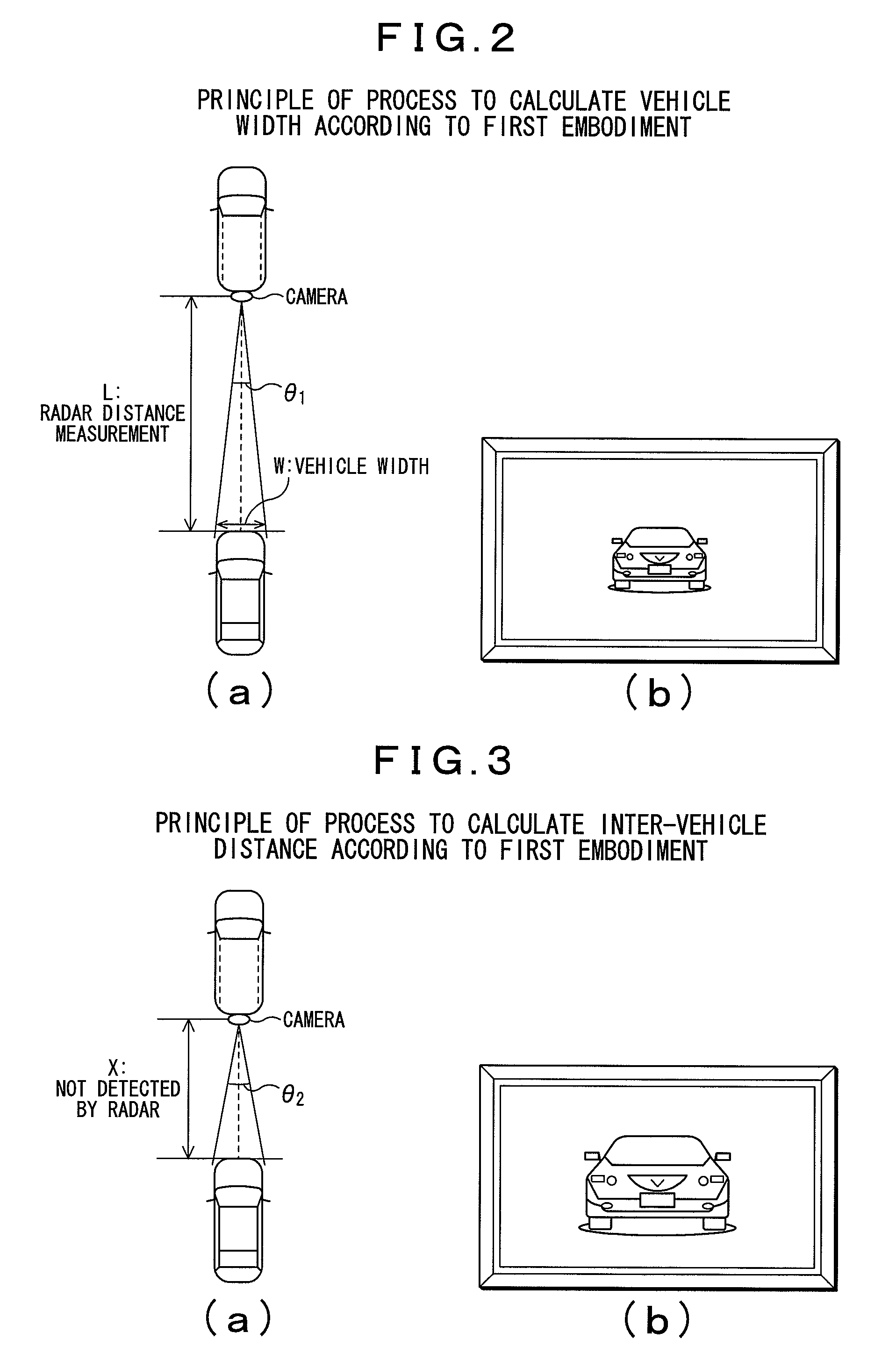
[0040]FIGS. 5(a) and 5(b) show a principle of an inter-vehicle distance detecting process according to the second embodiment, and a principle of a process to calculate a vehicle width of a neighboring vehicle. FIG. 5(a) shows a positional relationship between the user's own vehicle and a neighboring vehicle, and FIG. 5(b) shows an image taken by a camera 2.

[0041]According to the second embodiment, the image processing unit 3, upon the radar 1 detecting a neighboring vehicle, acquires a first visual angle θ3A which ranges from a direction orthogonal to an image plane of the camera 2 (direction toward the immed...


PUM


Abstract

There are provided an inter-vehicle distance detecting device and an inter-vehicle distance detecting method which can precisely measure an inter-vehicle distance from a user's own vehicle to a neighboring vehicle even if a radar becomes unable to detect the neighboring vehicle due to the influence of multipath or the like. If the radar does detect a neighboring vehicle, a width of the neighboring vehicle is calculated based on a precise inter-vehicle distance determined by the radar and a precise vehicle visual angle determined from an image taken by a camera, and is stored in a memory, and if the radar becomes unable to detect the neighboring vehicle, an inter-vehicle distance to the neighboring vehicle is calculated according to a trigonometric function based on the precise width of the neighboring vehicle previously stored in the memory and a precise vehicle visual angle determined from an image taken by the camera at this time.

Description

RELATED APPLICATIONS[0001]The present application claims priority to Japanese Patent Application Number 2005-350276, filed Dec. 5, 2005, the entirety of which is hereby incorporated by reference.BACKGROUND OF THE INVENTION[0002]1. Field of the Invention[0003]The present invention relates to an inter-vehicle distance detecting device and an inter-vehicle distance detecting method, and more particularly relates to a device which is preferably used to detect an inter-vehicle distance from a user's own vehicle to a neighboring vehicle by means of an onboard camera and an onboard radar.[0004]2. Description of the Related Art[0005]There recently have been provided systems which detect neighboring vehicles by means of onboard cameras and radars, show positional information on the detected neighboring vehicles to a user, and / or control steering according to the status of such information. There have also been provided systems which detect neighboring vehicles by means of cameras and radars,...

Claims


Application Information

Patent Timeline
Patent Type & Authority Patents(United States)
IPC IPC(8): G01S13/86G01S13/91G01S13/93G01S13/08G01S13/931
CPCG01S13/931G06K9/00805G01S13/867G06K2209/23G01S2013/9325G01S2013/9378G01S2013/93272G06V20/58G06V2201/08
Inventor MUNAKATA, KOHSUKE
Owner ALPINE ELECTRONICS INC
Why Eureka
Try Eureka