Tool and method for joining sidelapped joints of deck panels

a sidelap joint and sidelap technology, applied in the field of steel decking, can solve the problems of affecting the profit margin of the manufacturer, affecting the service life of the device disclosed in u.s. patent no. 6,212,932, and affecting the service life of the devi

Active Publication Date: 2008-10-14
VERCO DECKING
View PDF25 Cites 16 Cited by
  • Summary
  • Abstract
  • Description
  • Claims
  • Application Information

AI Technical Summary

Benefits of technology

[0022]The cutting edges of the first and second jaws are moved by the actuator within first and second planes, respectively. In one preferred embodiment of the invention, these first and second planes are generally co-planar for allowing the respective cutting edges to pass very closely to each other. Likewise, the cutting edges of the third and fourth jaws are moved by the actuator within third and fourth planes, respectively, and in one preferred embodiment, the third and fourth planes are generally co-planar for allowing the respective cutting edges to pass very closely to each other. In an alternate embodiment, the first and second planes, and the third and fourth planes, are intentionally spaced apart from each other to increase twisting deformation along the cut lines formed in the seam.
[0034]The central portion of the attachment that lies adjacent the first cut line is deformed in a first direction; on the other hand, the central portion of the attachment that lies adjacent the second cut line is deformed in a second opposing direction. The first outer portion of the attachment, lying adjacent the first cut line, is deformed in the second direction. Conversely the second outer portion of the attachment is deformed in the first direction. These attachments can be formed at regular intervals along the side-lapped seam to securely attach the first and second steel deck panels together.

Problems solved by technology

However, applicant has learned that the apparatus disclosed in U.S. Pat. No. 6,212,932 is subject to breakage when used on heavier gage decking.
Because of the significant stress borne by the single blade of the first jaw, such single blade can break, necessitating a stoppage of construction and associated scheduling delays for the user.
In addition, such breakage is a significant cost to the tool manufacturer, and related warranty claims detract from the manufacturer's profits.

Method used


Image

  • Tool and method for joining sidelapped joints of deck panels
  • Tool and method for joining sidelapped joints of deck panels
  • Tool and method for joining sidelapped joints of deck panels

Examples


Embodiment Construction

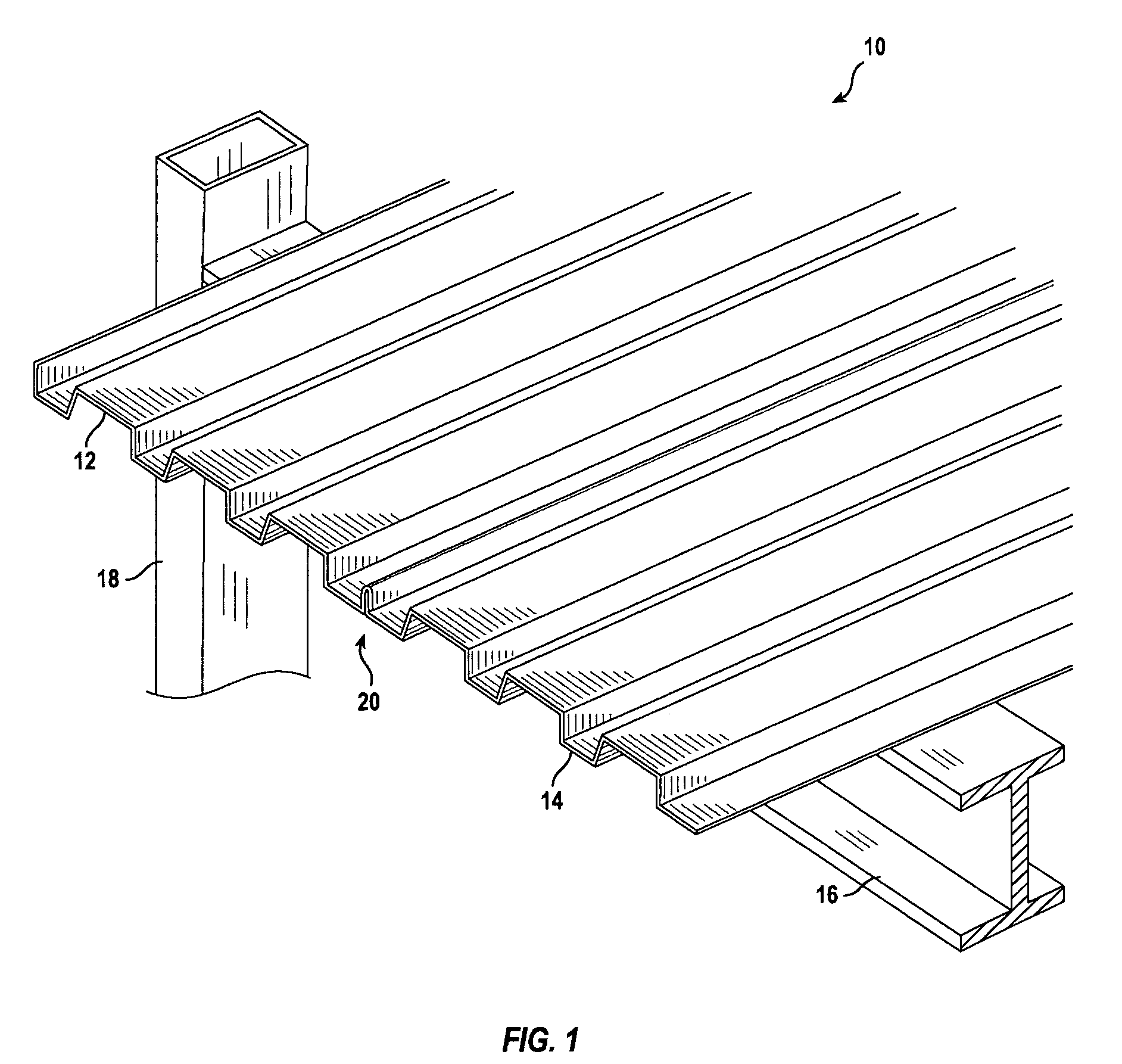
[0045]Referring to FIG. 1, a steel deck structure is designated generally by reference numeral 10 and includes at least a first fluted steel deck panel 12 and a second fluted steel deck panel 14. Deck panels 12 and 14 are welded or otherwise fastened to, and supported by, underlying horizontal steel support beams 16. In turn, horizontal steel support beams 16 are welded to, and supported by, vertical steel framing members 18, as is known in the art. Steel deck panels 12 and 14 are joined along a common longitudinal edge by a side-lapped seam 20, the details of which are described below. It will be sufficient to note here that side-lapped seam 20 should be secured in a manner which not only prevents the common longitudinal edges of panels 12 and 14 from separating from each other, but also prevents such common longitudinal edges of panels 12 and 14 from slipping or sliding longitudinally relative to each other.

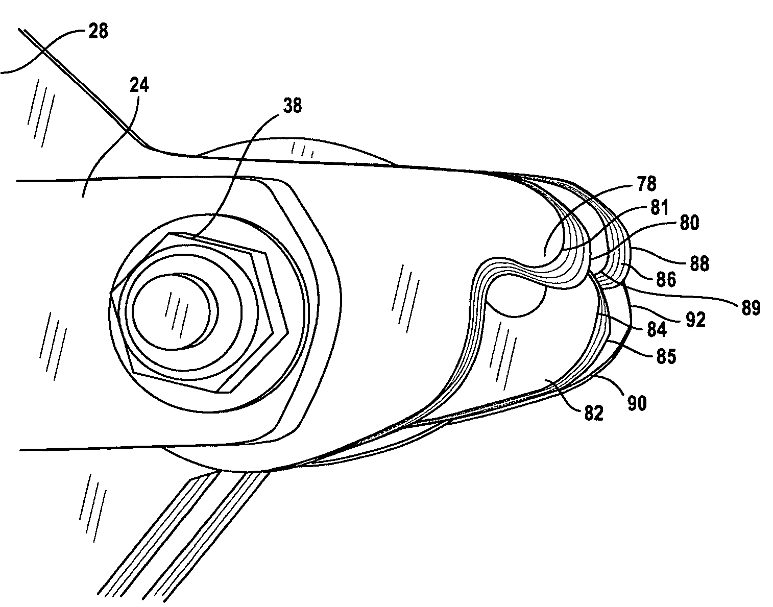
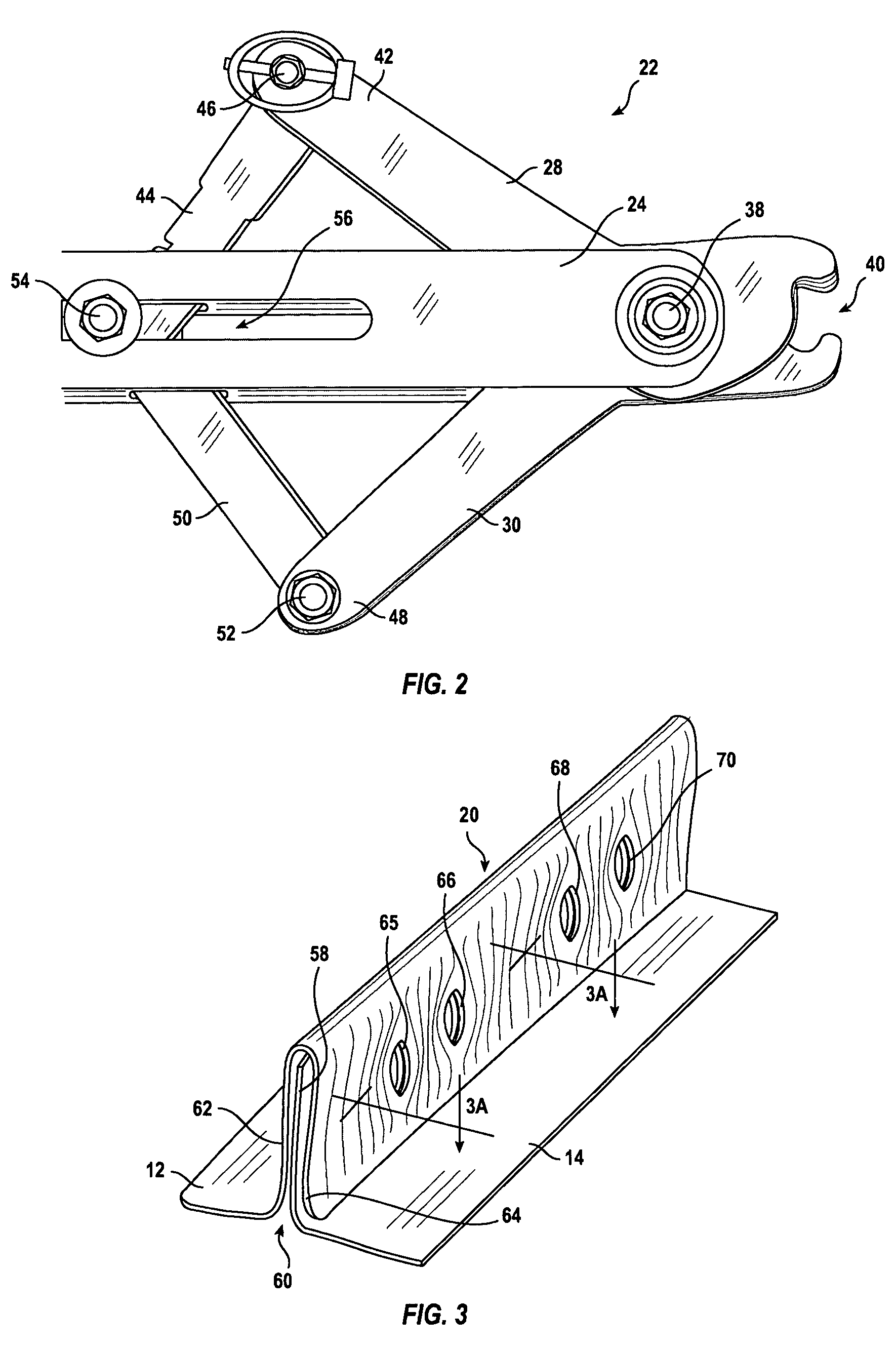
[0046]Turning to FIG. 2, a punching tool constructed in accordance with th...


PUM

PropertyMeasurementUnit
rotationaaaaaaaaaa
synchronized movementaaaaaaaaaa
thicknessaaaaaaaaaa

Abstract

A punching tool for forming an attachment in a side-lapped seam of steel decking includes four cutting jaws each having a cutting edge. Two jaws are positioned against one side of the seam, and two jaws are positioned on the opposite side of the seam. An actuator selectively pivots the cutting edges of opposing jaws generally toward each other to a closed position, driving the cutting edges of a first pair of jaws partially past each other for cutting a first slot through the seam, and driving the cutting edges of a second pair of jaws partially past each other for cutting a second slot through the seam. Also disclosed are a method for forming such an attachment, as well as the attachment structure which results therefrom.

Description

BACKGROUND OF THE INVENTION[0001]1. Field of the Invention[0002]The present invention relates generally to steel decking used to form flooring and roofing diaphragms of buildings, and more particularly, to a tool and method for reliably fastening together sidelapped edges of adjacent deck panels when constructing such building diaphragms.[0003]2. Description of the Related Art[0004]Fluted steel deck panels are well known in the art for constructing flooring and roofing of buildings. Examples of such fluted steel deck panels are shown, for example, in U.S. Pat. Nos. 4,186,535 and 4,894,967, both assigned to the assignee of the present application. Such steel deck panels are typically welded to underlying structural support beams. When properly assembled, such fluted steel deck panels provide a cost-effective diaphragm for floors and roofs, as well as relatively high horizontal shear values.[0005]Such fluted steel deck panels typically include first and second opposing sides that exte...

Claims


Application Information

Patent Timeline
Patent Type & Authority Patents(United States)
IPC IPC(8): B21D47/00B21D31/02B21J9/18B23P11/00B25B7/12B26B13/00E04D1/00
CPCB21D39/021B23D29/005Y10T29/53709Y10T29/49625Y10T29/53909Y10T29/49623Y10T29/49634Y10T29/53791Y10T29/539
Inventor MORTON, VIRGIL
Owner VERCO DECKING
Why Eureka
Try Eureka