Tool with enlarged hammer element

a tool and hammer element technology, applied in the field of hand tools, can solve the problems of low friction coefficient, slippage of the knife in the user's hand, and difficulty in holding the conventional taping knife during prolonged use, and achieve the effect of reducing the possibility of pinching the hand, and reducing the surface area

Active Publication Date: 2008-10-14
UNITED STATES GYPSUM CO
View PDF36 Cites 35 Cited by
  • Summary
  • Abstract
  • Description
  • Claims
  • Application Information

AI Technical Summary

Benefits of technology

[0006]The above-listed needs are met or exceeded by the present taping knife, which features an oversized hammer element attached to a lengthened handle shaft that holds the blade of the knife. The oversized hammer allows for greater ease of use for the end user given its relative size, providing more surface area to strike the drywall fastener, and a “baseball bat” type hammer shape that protrudes radially from the handle. This protrusion further acts as a buffer for the end user's hand when striking the wall, thus further reducing the possibility of pinching the hand. The taping knife also includes a handle made of inner and outer solid cores, with the outer core surrounding and interlocking with the inner core. The two solid cores are then covered with a resilient material for improved gripping characteristics and impact absorption.
[0007]The present handle also has a tapering neck allowing the end user to place his hand closer to the blade, thereby allowing greater control of the blade and its usage in the application of the joint compound to the wall and / or tape. This tapered neck is connected to a flared portion that tapers toward the blade at an angle that provides for a smooth transition, thereby also reducing the abrasion to the hand that can result from an abrupt transition from handle to blade, as found in conventional tools.

Problems solved by technology

However, the low coefficient of friction on the smooth outer surface of conventional handles allows slippage of the knife in the user's hand, particularly when the hand becomes wet from perspiration or joint compound.
Also, users with smaller hands have difficulty holding conventional taping knives during prolonged use.
While it is known to provide taping knives with a hammer element at the end of the handle for setting nails or other objects, many conventional knives do not have such hammer elements, and the knives that do typically have hammer elements that typically cap off the handle.
This improper use can cause the handle to crack, requiring the replacement of the knife.
Also, it is not uncommon for users' hands to slip on the handle during the hammering operation and become pinched between the tool and the wall.

Method used


Image

  • Tool with enlarged hammer element
  • Tool with enlarged hammer element
  • Tool with enlarged hammer element

Examples


Embodiment Construction

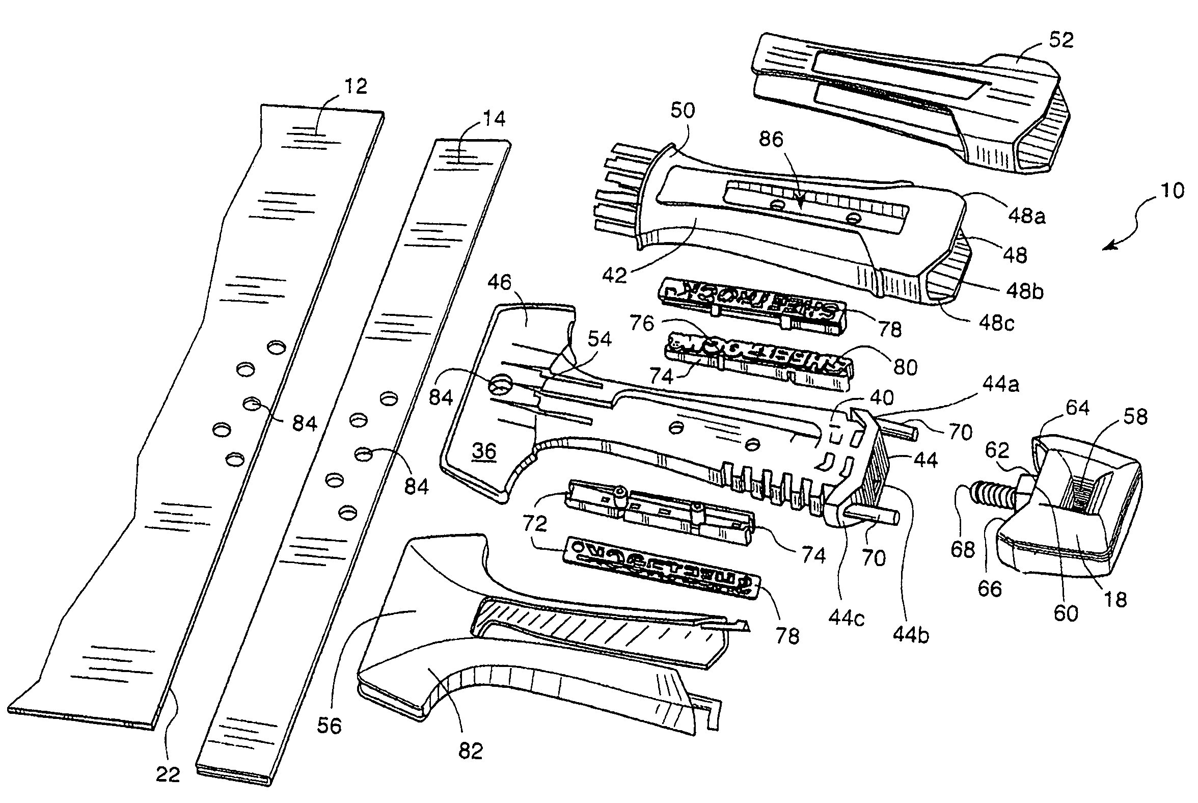
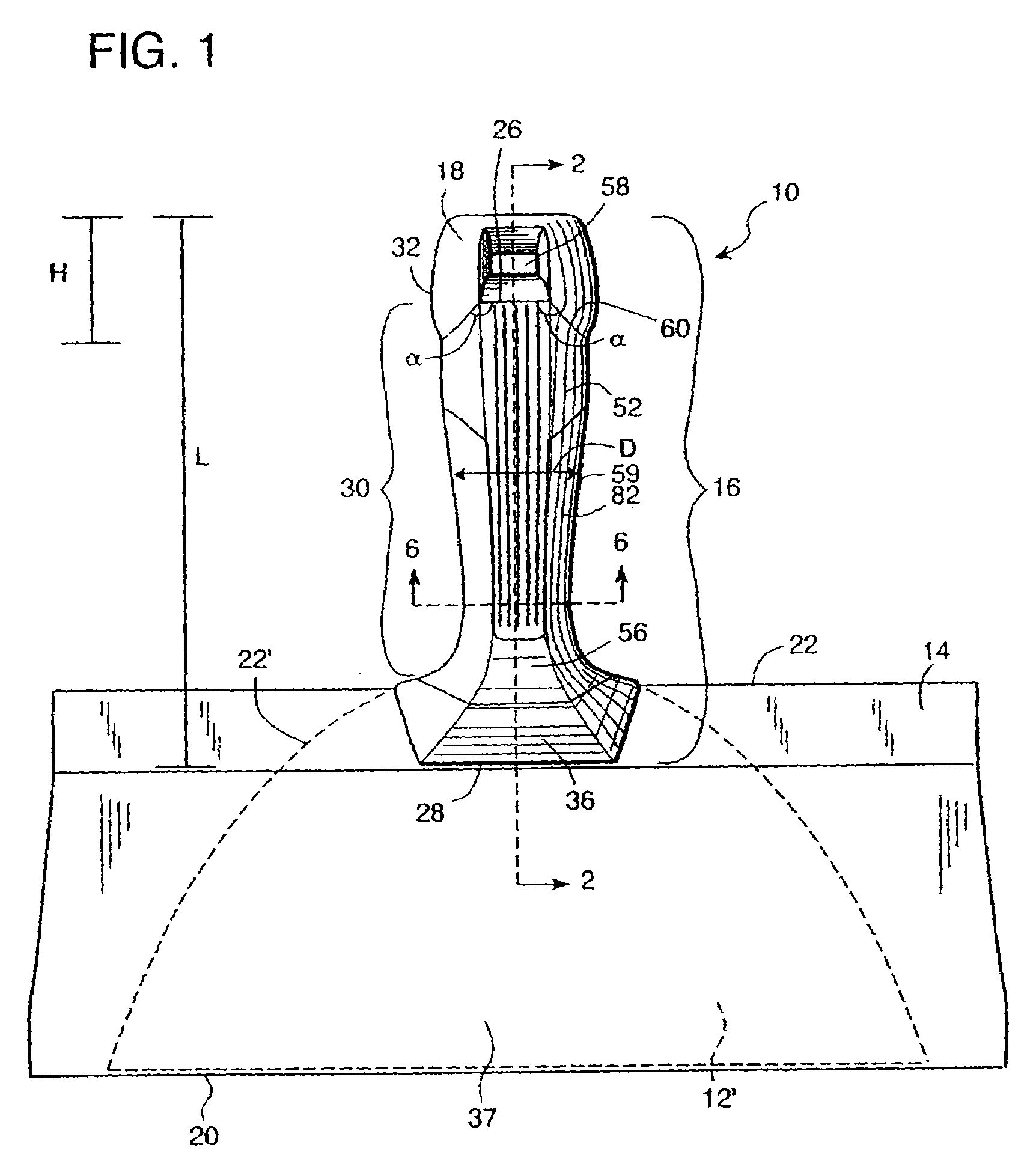
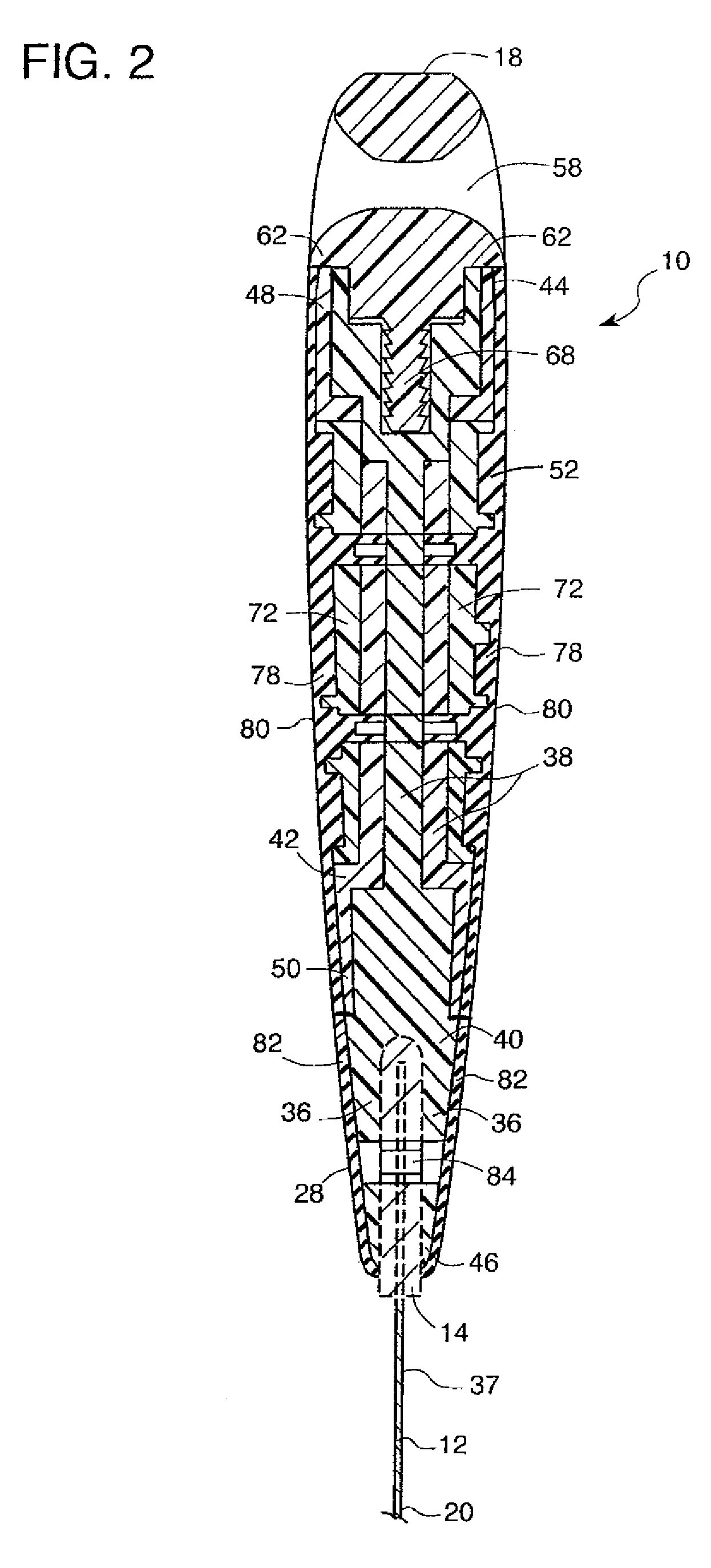
[0016]Referring to FIGS. 1 and 5, a taping knife generally designated 10 is preferably constructed of a flat metal blade 12, a reinforcing backing plate 14, a handle 16, and a hammer element 18. The blade 12 has a working edge 20 and an attachment edge 22 opposite the working edge 20. While other materials are contemplated, the blade 12 is preferably made of blued steel and the reinforcing backing plate 14 of aluminum. The shape of the blade 12 is as shown in FIG. 1, but it is envisioned that the handle 16 is usable with shorter blades 12′ having a curved attachment edge 22′ (shown in phantom in FIG. 1), and lacking a reinforcing backing plate 14 as are well known in the art. Furthermore, other blade shapes are contemplated, either with or without a reinforcing backing plate 14.

[0017]The handle 16 has at least one diameter D and includes distal 26 and proximal ends 28 and a body 30, the proximal end 28 is associated with the attachment edge 22. A feature of the present knife 10 is t...


PUM


Abstract

A tool includes a blade having a working edge and an attachment edge opposite the working edge, a handle with distal and proximal ends and a body having at least one diameter. The proximal end is associated with the attachment edge. A hammer element is associated with the distal end, and a periphery of the hammer element extends in a radial direction greater than the at least one diameter of the body.

Description

BACKGROUND OF THE INVENTION[0001]The present invention generally relates to hand tools, and more particularly to a taping knife of the type used to finish drywall construction projects.[0002]Taping knives or tools (the terms are considered interchangeable), which have varying blade widths, are used to finish drywall construction projects and create a smooth transition between abutting drywall surfaces. After drywall boards are in place, a smaller (e.g. 4-6 inch) taping knife is generally used to apply a settable joint compound and drywall tape to the joints formed by the abutting drywall surfaces. At this stage, unseated nails must also be finally set into the wallboards and supporting studs. After the joint compound dries, progressively larger (e.g. 8 inch-14 inch) knives are used to apply more compound to the joint areas. This step is repeated, with intermittent sanding steps, until the joint is sufficiently flat and smooth.[0003]Present taping knives often use wood or plastics, s...

Claims


Application Information

Patent Timeline
Patent Type & Authority Patents(United States)
IPC IPC(8): B26B3/00A47L13/022
CPCE04F21/06Y10T16/476Y10T16/48Y10S16/902
Inventor PEREZ, RICARDOLIND, JASONMYERS, MATTHEW EARLEFONG, SCOTT
Owner UNITED STATES GYPSUM CO
Why Eureka
Try Eureka