Method and apparatus for tire uniformity measurement

a technology of uniformity and measurement method, applied in the direction of instruments, applications, roads, etc., can solve the problems of vehicle oscillation and noise inside the vehicle, the difficulty of mass production of such an ideal tire, and the difficulty of mass production of such ideal tires

Active Publication Date: 2008-10-14
KOKUSAI KEISOKUKI KK
View PDF10 Cites 15 Cited by
  • Summary
  • Abstract
  • Description
  • Claims
  • Application Information

AI Technical Summary

Benefits of technology

[0009]An aspect of the present invention relates to detect the fluctuation in the exciting force produced by nonuniformity in a tire lateral direction (i.e., a direction of the tire rotational axis). That is, when exciting forces are produced by nonuniformities of opposite phases on both sides of the tire in the lateral direction, these exciting forces of opposite phase canceled each other out during the detection if the measurement is based on the “disc model”. These exciting forces of opposite phase may not be cancelled and may be applied to the vehicle shaft. Thus, according to an embodiment of the invention, it becomes possible to detect an index which can pick up tires which may produce vibrations of the vehicle chassis and noise inside the vehicle, even if exciting forces of opposite phases occur on the two sides of the tire in the lateral direction.

Problems solved by technology

However, the usual tire construction and manufacturing process make it difficult to mass produce such an ideal tire.
Recently, a problem has occurred in that even when nonuniformity as measured by the uniformity measurement method described above is judged to be within tolerable limits, particularly in high speed vehicle operation, an exciting force from a tire is sometimes applied to the vehicle shaft, causing vehicle oscillations and noise inside the vehicle.
The cause of these oscillations and noise is considered to be nonuniformity that could not be evaluated from the result of measurement by the conventional uniformity measurement method.

Method used


Image

  • Method and apparatus for tire uniformity measurement
  • Method and apparatus for tire uniformity measurement
  • Method and apparatus for tire uniformity measurement

Examples


first embodiment

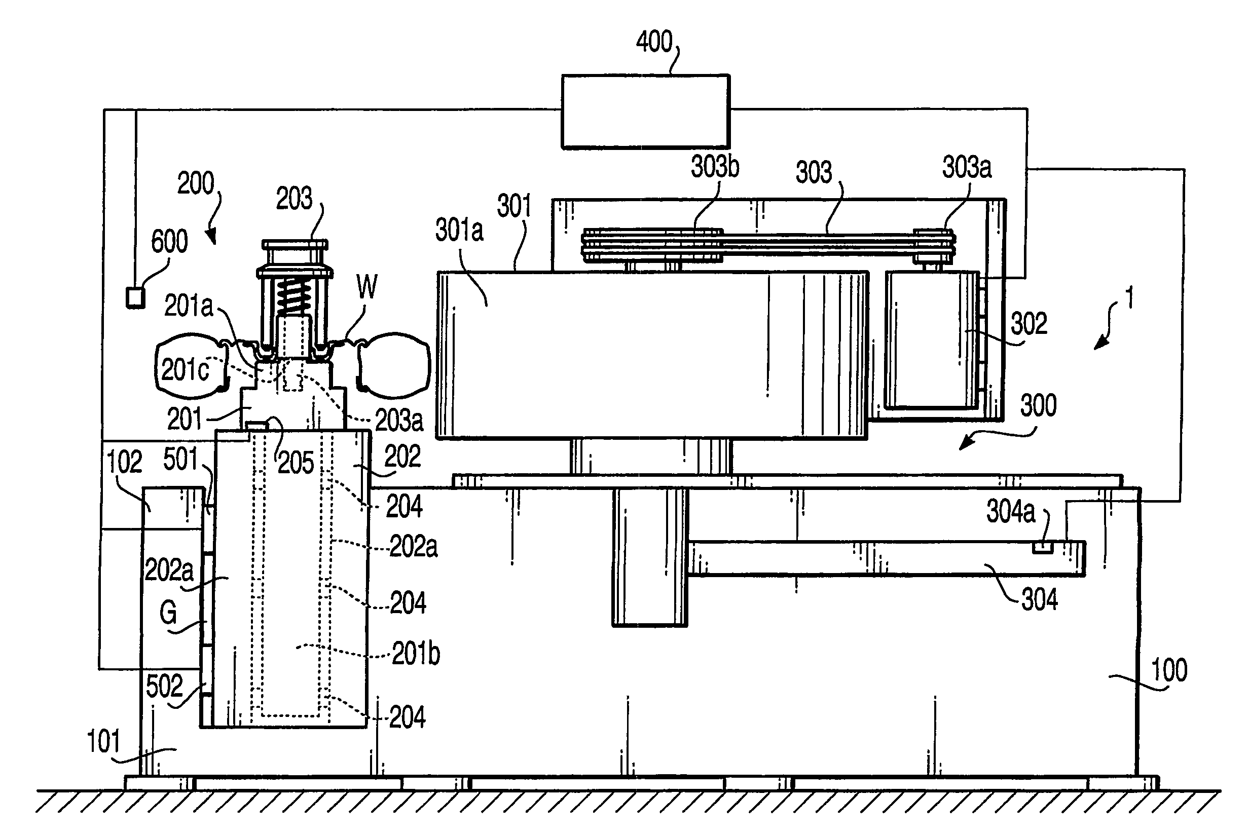
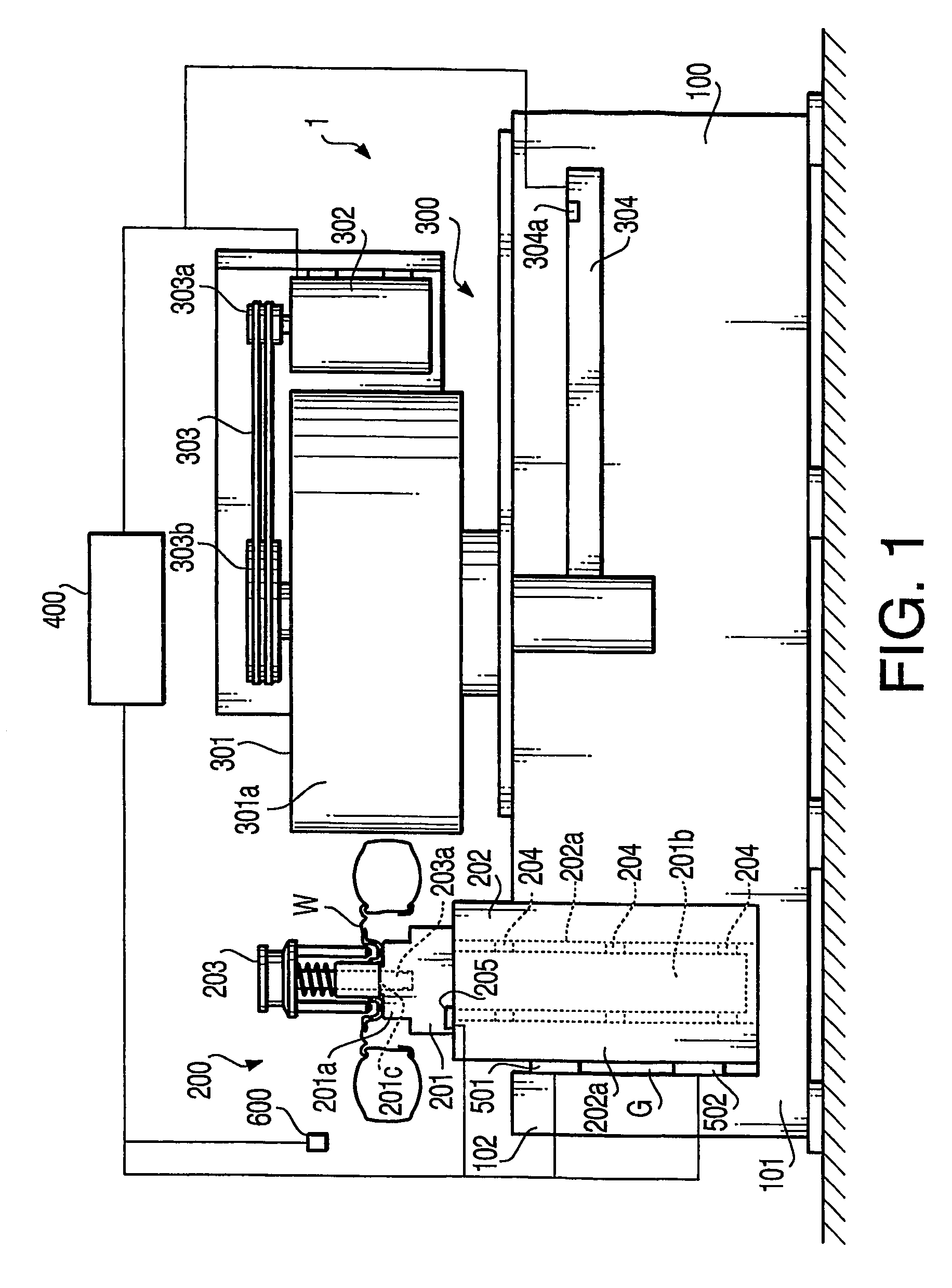
[0033]FIG. 1 shows a front view of a high-speed tire uniformity measurement apparatus which is an embodiment of this invention. The measurement apparatus 1 which is an embodiment of this invention measures the high-speed uniformity of the tire, the uniformity according to JAS 0 C 607 standard, and the tire dynamic balance. In addition, it includes a marking apparatus which can mark the tire for use in removing tire unbalance. Dynamic balance is measured by rotating the tire in free rotation and measuring the centrifugal force that arises at that time. In this invention, the tire is rotated together with a rotating drum, with the rotating drum pressed against the tire tread surface. The pressing force which presses the tire against the rotating drum is set small, to 50 to 80 [kgf]. Among the forces acting on the tire, fluctuation of a component perpendicular to the tire rotational axis and the direction in which the tire is pressed, is measured. These fluctuation does not include the...

second embodiment

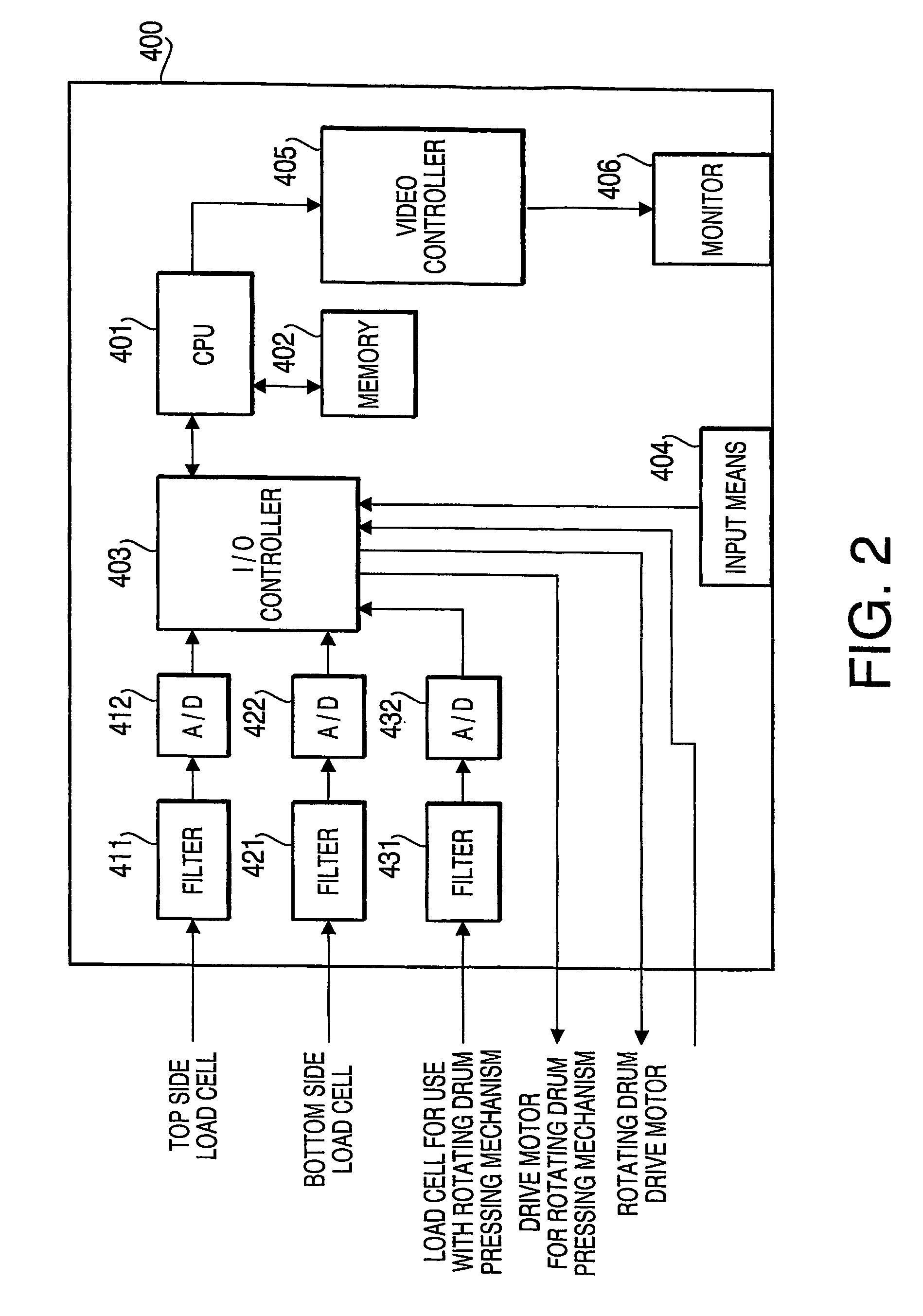
[0103]FIG. 4 is a time chart showing the measurement procedure for measuring the dynamic balance and uniformity of a tire using the measurement apparatus 1 in the second embodiment. In this embodiment, a high speed uniformity test and a uniformity test according to the JASO C607 standard are performed on one tire. After the high speed uniformity measurement, depending on the result a dynamic balance test is performed. Similarly to FIG. 3, FIG. 4 is a time chart having elapsed time as the abscissa and tire rotational rate as the ordinate. The series of tests described below are carried out by execution of programs stored in the memory (FIG. 2) of the measurement apparatus 1 by the CPU 401. In addition, before the measurements, calibrations similar to those in the first embodiment are performed.

[0104]First, the tire is attached to the spindle 301, and the tire is fixed to the spindle 201 by the top adapter 203.

[0105]Next, the tire is pushed into contact with the rotating drum 301. Nex...


PUM

PropertyMeasurementUnit
pressing forceaaaaaaaaaa
forceaaaaaaaaaa
forceaaaaaaaaaa

Abstract

There is provided a method and a apparatus for measuring tire uniformity. The apparatus comprises a spindle, a rotating drum, a sensor and a computing means. The method comprises the steps of mounting a tire on the spindle, pressing a circumferential surface of a rotating drum against the tread surface of the tire with a first pressing force, rotating the tire around rotational axis thereof, and computing the forces which the tire acts on first and second planes of the tire by the computing means while the tire is rotating. The first plane is perpendicular to the rotational axis and in one sidewall side of the tire. The second plane is perpendicular to the rotational axis and in the other sidewall side of the tire. The forces are computed based on values obtained by the sensor measuring forces transmitted to the spindle from the tire at first and second positions. The first and second positions have different distances from the tire in the rotational axis direction.

Description

FIELD OF THE INVENTION[0001]This invention relates to a method and an apparatus for tire uniformity measurement.BACKGROUND OF THE INVENTION[0002]Ideally, a tire is desirable to be a perfect circle, and interior stiffness, dimensions and weight distribution and other features thereof should be uniform around the circumference of the tire. However, the usual tire construction and manufacturing process make it difficult to mass produce such an ideal tire. That is, a certain amount of nonuniformity in the stiffness, dimensions and weight distribution and other features occur in the produced tire. As a result, an exciting force is produced in the tire while the vehicle is running. The oscillations produced by this exciting force are transmitted to the vehicle chassis and cause a variety of vehicle oscillations and noises including shaking, fluttering, sounds of the tire vibrations being transmitted inside the vehicle, and beat sounds.[0003]One known method for evaluating nonuniformity of...

Claims


Application Information

Patent Timeline
Patent Type & Authority Patents(United States)
IPC IPC(8): G01M17/02E01C23/00G01M1/16B60C19/00
CPCG01M17/022B29D2030/0634B60C25/002B60Y2304/09G01M1/34
Inventor MATSUMOTO, SIGERU
Owner KOKUSAI KEISOKUKI KK
Why Eureka
Try Eureka