Rotary engine

a rotary engine and rotor technology, applied in the direction of liquid fuel engines, machines/engines, combination engines, etc., can solve the problems of 20° of contact angle between the inner circumferential contact wall, inability to maintain perfect air tightness, and inability to achieve perfect air tightness, improve sealing performance, and improve fuel combustion efficiency

Active Publication Date: 2008-10-14
CHAE ON SOON
View PDF29 Cites 8 Cited by
  • Summary
  • Abstract
  • Description
  • Claims
  • Application Information

AI Technical Summary

Benefits of technology

[0011]Therefore, the present invention has been made in view of the above problems, and it is an object of the present invention to provide a rotary engine in which a contact angle between the inner circumferential contact wall of a cylinder chamber and a seal face of a rotor is continuously kept at a constant value to improve sealing performance, thereby achieving only slight even wear in the inner circumferential contact wall of the cylinder chamber and achieving an enhancement in the efficiency of fuel combustion and an enhancement in engine output.
[0012]It is another object of the present invention to provide a rotary engine capable of preventing gas mixture, which leaks during a compression stroke, from being discharged in an uncombusted state, thereby preventing waste of fuel and air pollution.
[0013]It is yet another object of the present invention to provide a rotary engine in which gas mixture, which leaks during a compression stroke, is supercharged in an intake stroke rather than being exhausted, thereby achieving an enhancement in the efficiency of fuel combustion and an enhancement in engine output.

Problems solved by technology

However, the rotary engine, having the above described configuration, has a problem in that a contact angle between the inner circumferential contact wall of the cylinder chamber and a seal face of the rotor for the maintenance of air-tightness greatly varies in a range of ±20°.
Also, it is impossible to maintain perfect air-tightness because the inner wall of the cylinder chamber shows uneven wear differently from the piston reciprocating engine, and, in particular, it is difficult to maintain air-tightness during a compression stroke.
This is a representative disadvantage occurred in most rotary engines.
Due to the imperfect air-tightness between the inner circumferential contact wall of the cylinder chamber and the seal face of the rotor, the conventional rotary engine suffers from degradation in engine performance, and causes gas mixture to leak during the compression stroke to thereby be exhausted in uncombusted state.
This disadvantageously results in waste of fuel and air pollution.

Method used


Image

  • Rotary engine
  • Rotary engine
  • Rotary engine

Examples


first embodiment

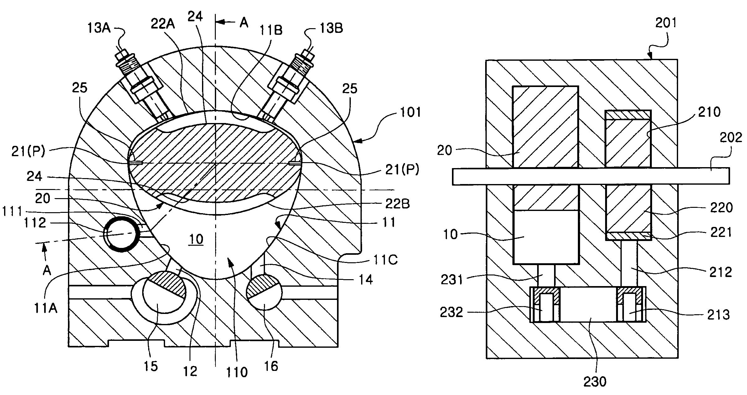
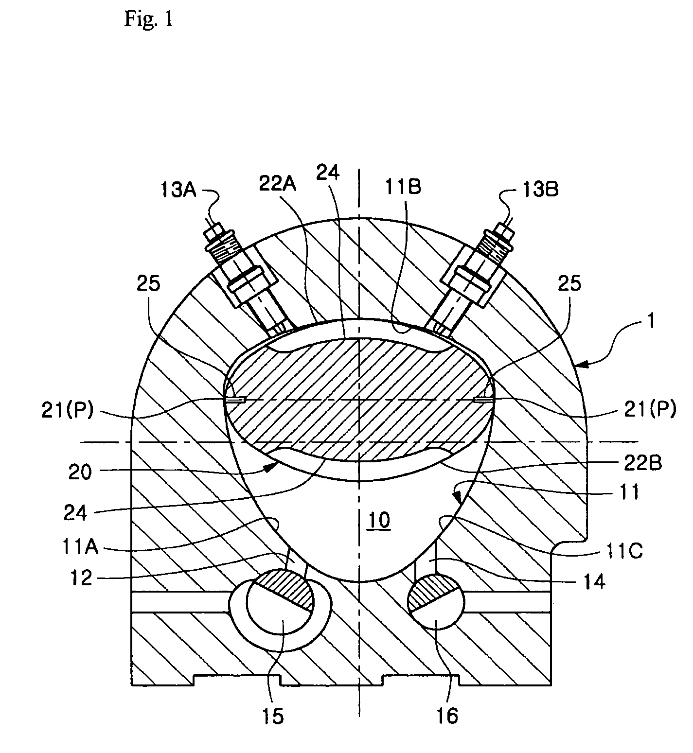
[0030]FIG. 1 is a schematic configuration diagram illustrating a rotary engine according to the present invention. As shown in FIG. 1, the rotary engine according to the present embodiment comprises a cylinder body 1 having a cylinder chamber 10, and a rotor 20, which is received in the cylinder chamber 10 to eccentrically rotate.

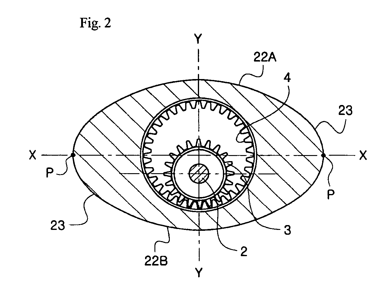
[0031]The rotor 20 has an elliptical shape, and is provided at opposite apexes P thereof in a direction of a major axis X-X with seal faces 21, which come into contact with an inner circumferential contact wall 11 of the cylinder chamber 10. The cylinder chamber 10 has the same shape as a specific curve which is described by the opposite apexes P when the rotor 20 eccentrically rotates. The inner circumferential contact wall 11 of the cylinder chamber 10 includes arcuate first to third sides 11A to 11C, and connecting portions between the respective edges of the first to third sides 11A to 11C are curved, whereby the inner circumferential contact wall 11 ha...

second embodiment

[0051]The rotary engine according to the present invention comprises a cylinder body 101 having two cylinder units, i.e. first and second cylinder units 110 and 120, which are arranged in parallel to each other in an axial direction of an output shaft 102. The rotary engine further comprises a pair of rotors 20, which are received in the first and second cylinder units 110 and 120, respectively, to cross each other with a phase difference of 90°.

[0052]The first and second cylinder units 110 and 120 have superchargers 111 and 121, respectively. The superchargers 111 and 121 are located between the intake port 12 and the spark plug 13A of the respective cylinder chambers 10, i.e. at the first side 11A of the respective cylinder chambers 10. As shown in FIG. 5, the superchargers 111 and 121 are connected to each other through a bypass channel 113 provided in the cylinder body 101.

[0053]The superchargers 111 and 121 are provided with opening / closing valves 112 and 122, respectively. Ref...

third embodiment

[0086]With the supercharging means according to the present invention, the uncombusted gas, which leaks from between the inner circumferential contact wall 11 of the cylinder chamber 10 and the seal members 25 during the compression stroke and remains in the section A of the cylinder chamber 10, is charged into the supercharging chamber 210. After being temporarily stored in the supercharging chamber 210, the uncombusted gas is able to be returned from the supercharging chamber 210 into the cylinder chamber 10 during the intake stroke of the cylinder chamber 10. This effectively increases the intake amount of the gas mixture while preventing discharge of the uncombusted gas to the outside, thereby achieving an enhancement in generation of rotational power in an expansion stroke and preventing waste of fuel and air pollution.

[0087]In the preferred embodiments of the present invention as described above, the rotary engine is configured to have a single cylinder unit, two cylinder unit...


PUM


Abstract

The rotary engine includes a cylinder body having a cylinder chamber, an intake port, an exhaust port, and a spark plug, and a rotor which is received in the cylinder chamber to eccentrically rotate while coming into contact at seal faces thereof with an inner circumferential contact wall of the cylinder chamber to thereby implement intake, compression, expansion, and exhaust strokes. The rotor has an elliptical outer contour, and the inner circumferential contact wall of the cylinder chamber coincides with a specific curve, which is described by opposite apexes of the elliptical rotor in a direction of a major axis, when the rotor eccentrically rotates. The intake port and exhaust port are provided with opening / closing valves, respectively. Sealing performance between the cylinder chamber and the rotor may achieve an enhancement in the efficiency of fuel combustion and engine output and prevent waste of fuel.

Description

BACKGROUND OF THE INVENTION[0001]1. Field of the Invention[0002]The present invention relates to a rotary engine, and, more particularly, to a rotary engine which can improve sealing performance between an inner circumferential contact wall of a cylinder chamber and a seal face of a rotor that comes into contact with the inner circumferential contact wall and can minimize leakage of gas mixture during a compression stroke to reduce exhaust gas, thereby achieving an enhancement in engine output and an enhancement in fuel efficiency.[0003]2. Description of the Related Art[0004]A rotary engine is designed to obtain rotational power by performing four strokes, for example, intake, compression, expansion, and exhaust strokes, as in a piston reciprocating engine. However, the rotary engine clearly differs from the piston reciprocating engine in the structure of a mover which is used to induce the four strokes. In the piston reciprocating engine, the four strokes are induced as the recipro...

Claims


Application Information

Patent Timeline
Patent Type & Authority Patents(United States)
IPC IPC(8): F02B53/00F01C1/063
CPCF01C11/002F02B53/04F02B55/02F02B55/14F01C1/104F02B2730/018Y02T10/17Y02T10/12F02B55/08
Inventor KIM, HEON KYU
Owner CHAE ON SOON
Why Eureka
Try Eureka