Lighting system and optical projection structure therefore

a technology of optical projection and light source, which is applied in the direction of lighting and heating apparatus, semiconductor devices for light sources, lighting applications, etc., can solve the problems of limited life of lamps, insufficient illumination of decks, and inconvenient use, so as to achieve cost-effective, effective illumination of decks, and friendly to nvgs

Inactive Publication Date: 2008-10-14
BREAULT RES ORG
View PDF10 Cites 5 Cited by
  • Summary
  • Abstract
  • Description
  • Claims
  • Application Information

AI Technical Summary

Benefits of technology

[0007]According to the present invention, a lighting system comprises at least a pair of lighting subsystems that project light to a volume space with different spatial distributions. One subsystem projects light to the volume space with a predetermined spatial distribution, and the other lighting subsystem projects light to the volume space with a different spatial distribution, in a manner that effectively supplements the projected light from the first subsystem, so as to provide a lighting system that effectively illuminates the entire volume space.
[0009]Moreover, the system is designed to be particularly compatible with the optical capabilities of night vision goggles. The system is designed to substantially filter out light in a predetermined wavelength band that is “out of band” of night vision goggles (i.e. the wavelength band at which night vision goggles operate), so that the projected light effectively illuminates the deck, and does not interfere with the vision of pilots who are using night vision goggles.
[0010]In addition, the lighting system of the present invention is designed to be optically efficient, provide uniform illumination, and be friendly to NVGs and to be cost effective.
[0011]Still further, the principles of the present invention, while particularly useful in illuminating a ship deck, can also be used in other types of environments where illumination of a volume space in a manner that also minimizes projection of light in a wavelength band that can have adverse effect for the system is desirable. For example, street lighting systems that also need to minimize light pollution (e.g. because of optical devices in an area of interest) can benefit from the principles of the present invention.
[0012]Furthermore, the present invention provides a new and useful optical projection structure, that is particularly useful in projecting light from a source (e.g. an array of light emitting diodes [“LEDs”]) to a volume space, while minimizing the overall size of the projection structure, and maintaining good projection efficiency. The light projection structure comprises a curved reflector segment and a refractor. The curved reflector segment and refractor are in a predetermined light collection relationship to each other, and the source has a predetermined location and angular relation to the curved reflector segment and the refractor that is at least partially based on the focal points of the curved reflector segment and refractor and the light collection relationship of the curved reflector segment and the refractor.

Problems solved by technology

While these systems provide illumination over a broad area, they are deficient in a number of ways.
One of the primary issues is that they do not uniformly illuminate the deck.
In addition, incandescent lamps have limited lifetimes so regular maintenance must be done frequently and the risk of having a deck lamp fail is undesirably high.
An additional problem with current deck lamps is that too much light is directed off of the deck.
Finally, current deck lamps produce a significant amount of light that can be detected by night vision goggles (NVGs) which makes NVGs difficult to use.
Attempts have been made to insert filters over the deck lamps to allow pilots landing on ships to use NVGs while personnel on the ship still have an adequate level of illumination, but the results are inadequate.
In the applicant's experience, illuminating a ship deck, particularly a ship deck that aircraft may be taking off from and landing on at all hours, presents a number of challenges.

Method used


Image

  • Lighting system and optical projection structure therefore
  • Lighting system and optical projection structure therefore
  • Lighting system and optical projection structure therefore

Examples


Embodiment Construction

[0022]As discussed above, the present invention provides a new and useful lighting system that is particularly useful as a lighting system for a deck (e.g. a ship deck), and to an optical projection structure that is particularly useful in such a system. The principles of the present invention are described herein in connection with a ship deck lighting system that is designed to illuminate the center of the deck, without interference with pilots' night vision goggles. However, from that description, the manner in which the principles of the present invention can be used with various types of lighting systems will be apparent to those in the art.

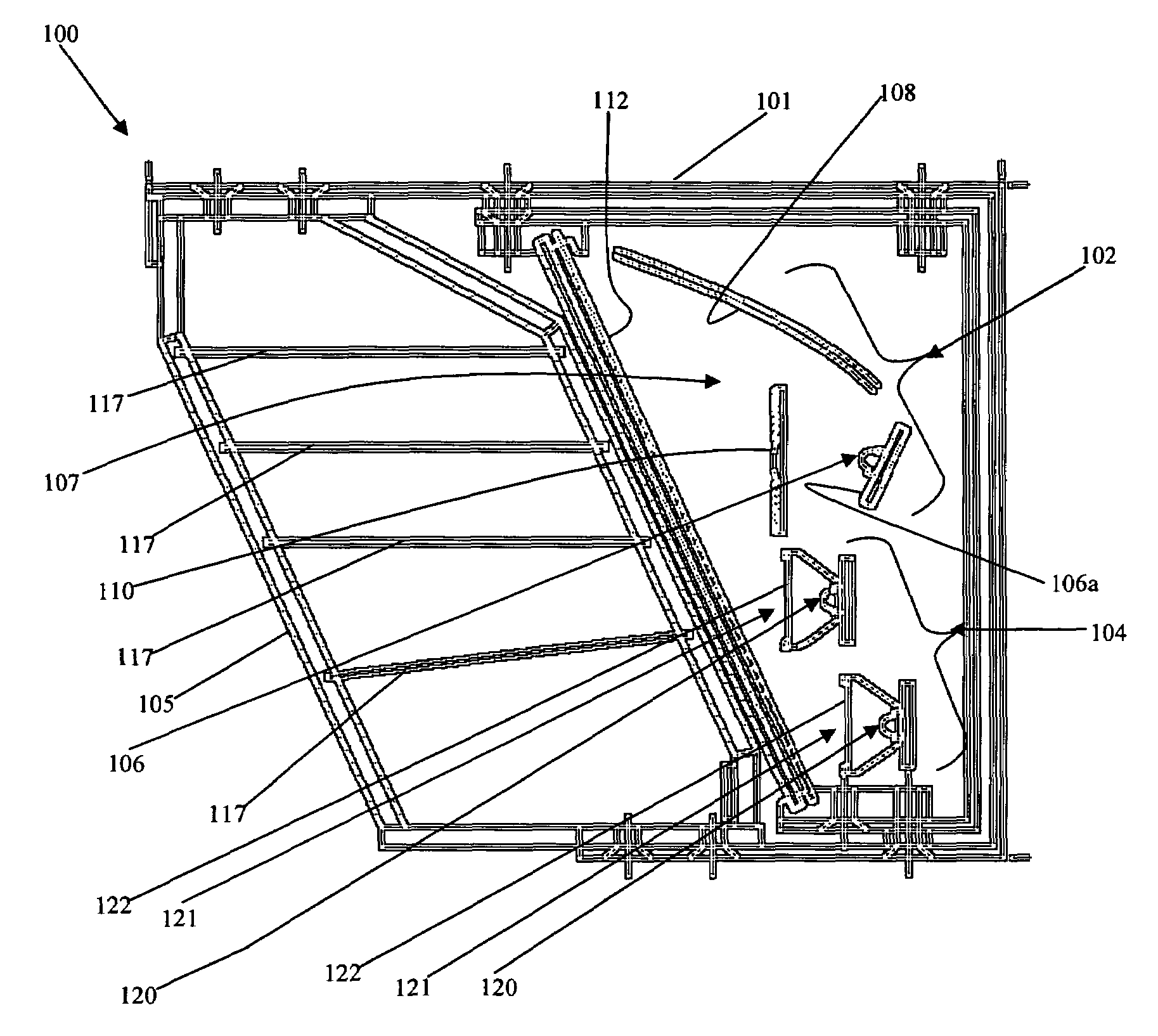
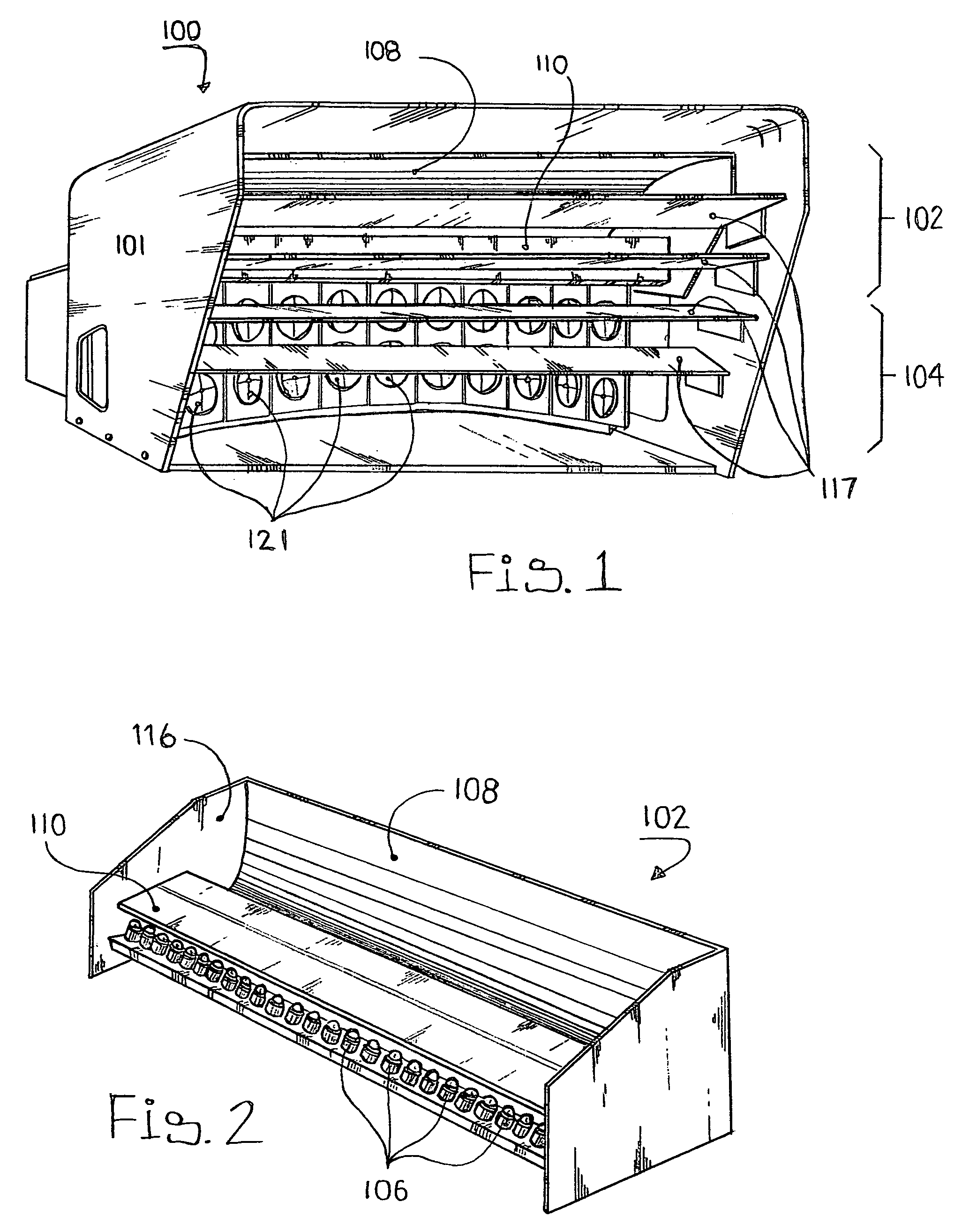
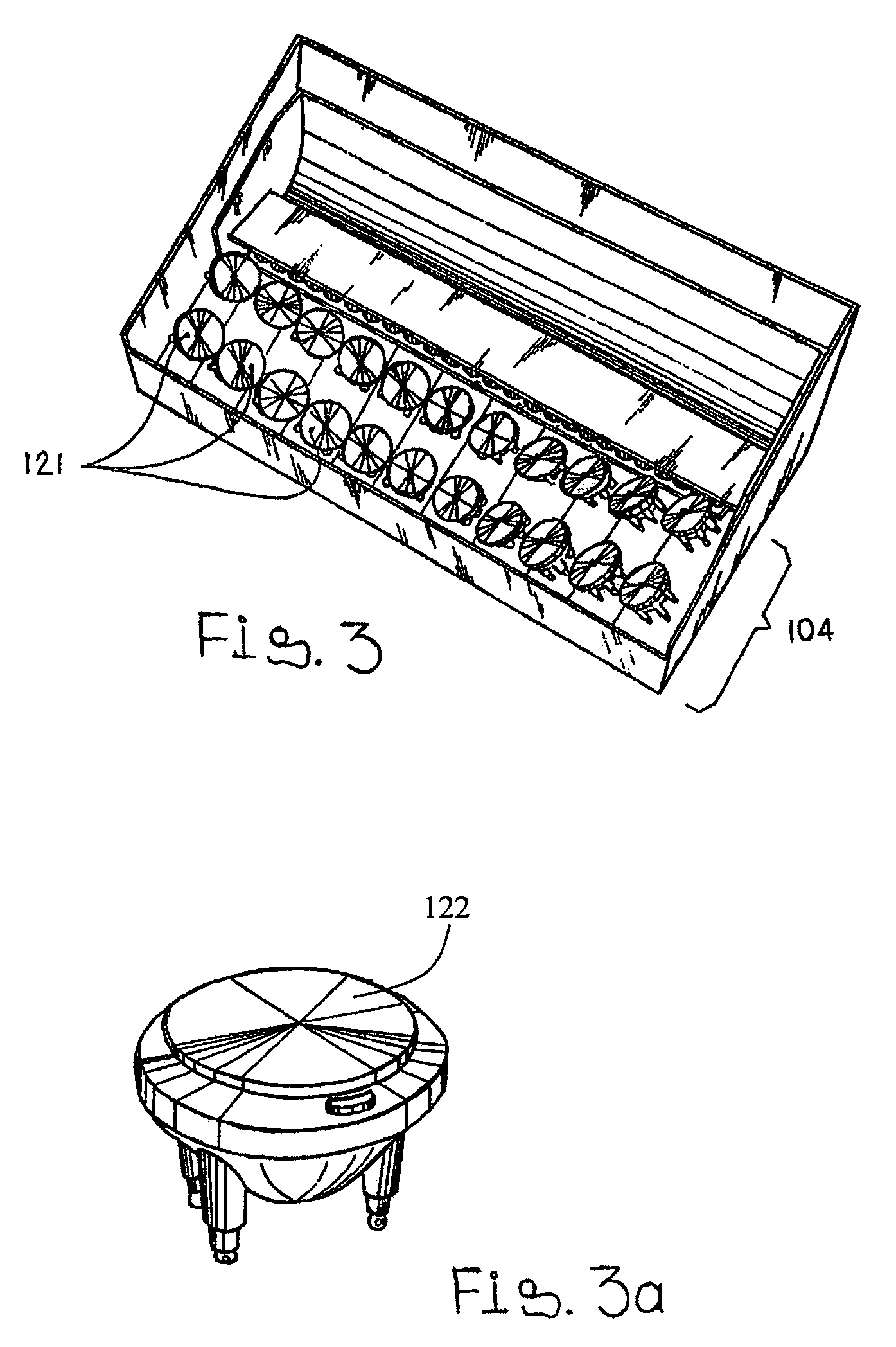
[0023]A deck lighting system according to the present invention is shown at 100.

[0024]The lighting system 100 includes a housing 101 with pair of lighting subsystems 102, 104 therein, and a protective glass cover 105. The lighting subsystem 102 projects light to a deck with a predetermined spatial distribution. The lighting subsystem 104 pro...


PUM


Abstract

A new lighting system is provided that is particularly useful in projecting light to a deck where pilots use night vision goggles (NVGs). The system comprises a pair of subsystems that project light with different, complementary spatial distributions. One subsystem projects light with one spatial distribution, and the other lighting subsystem projects light with another spatial distribution that supplements the light from the first subsystem, so as to provide a system that effectively illuminates an entire target. The system is designed to substantially filter light so that the light does not interfere with NVGs. The system includes new optical projection structure that minimizes the overall size of the projection structure, and maintains good efficiency.

Description

GOVERNMENT RIGHTS[0001]This invention may have been at least partially supported by funding under U.S. government SBIR Contract No. N65538-04-M-0098 awarded by the Department of the Navy, Naval Sea Logistics Center (NAVSEA). The government may have some rights in this invention.BACKGROUND[0002]The present invention relates to a new and useful lighting system that is particularly useful as a floodlighting system for a space such as the deck of a ship, and to a new and useful optical projection structure for a lighting system.[0003]Current deck lamps use incandescent lamps with reflectors. While these systems provide illumination over a broad area, they are deficient in a number of ways. One of the primary issues is that they do not uniformly illuminate the deck. Directly in front of each lamp is a bright spot and the brightness decreases significantly as the distance in increased. In addition, incandescent lamps have limited lifetimes so regular maintenance must be done frequently an...

Claims


Application Information

Patent Timeline
Patent Type & Authority Patents(United States)
IPC IPC(8): H01G5/06
CPCB63B45/06F21V7/04F21V9/00F21V13/12F21V14/08F21W2131/103F21W2131/40F21Y2101/02F21Y2115/10
Inventor KAMINSKI, MARK E.DUBIN, MATTHEW BFINK, MARK R.
Owner BREAULT RES ORG
Why Eureka
Try Eureka