System and method of using a multi-view display

a multi-view display and display system technology, applied in the field of vehicle display systems, can solve the problems of increasing the complexity of automation, crowding and complicating the flight deck instrument panel, and increasing the cost of flight deck space, so as to increase the effective display space

Inactive Publication Date: 2008-01-03
GENERAL DYNAMICS GULFSTREAM AEROSPACE
View PDF37 Cites 26 Cited by
  • Summary
  • Abstract
  • Description
  • Claims
  • Application Information

AI Technical Summary

Benefits of technology

[0011]In accordance with some embodiments of the invention, a multi-view technology may be employed in vehicles having displays systems, such that a single display device may function as two simultaneous displays. The single display device may be configured with two different viewing envelopes. Each viewing envelope defines a three-dimensional space within which an associated image on the display device is visible. By employing the multi-view technology in accordance with embodiments of the invention, a vehicle may significantly increase the effective display space by dedicating a first image, and associated viewing envelope, with a first crew member and dedicating a second image, and associated viewing envelope, with a second crew member.
[0013]In one embodiment of the invention, two multi-view displays may be employed with any associated aircraft system controller that combines multiple functions into a single device. To maximize instrument panel real estate and minimize pilot workload while maintaining compliance with FAR regulations, multifunctional instruments (system controllers and displays), combined with standby instruments, may be used as discussed in one embodiment disclosed in U.S. patent application Ser. No. 11 / 172,925, filed Jul. 5, 2005, which is assigned to the assignee of the present invention and hereby incorporated by reference in its entirety. By combining the multi-view technology into the multifunction controllers and associated displays, each associated display may function to display two images, one in each of two different viewing envelopes. For each display, the two images may be referenced as an on-side image or view and a cross-side image or view. The on-side view may be associated with a viewing envelope directed at the side of the aircraft that the display is installed on and a cross-side view may be associated with a viewing envelope directed at the side of the aircraft opposite of the display. Each on-side view may be controlled by an associated crew member or pilot, located in the associated viewing envelope, to access information from the various data sources. Each cross-side view may be controlled by another crew member or pilot, located in the associated viewing envelope, or may be configured to always display the standby indications, thereby satisfying FAR regulations concerning the standby instruments.

Problems solved by technology

As such, flight deck space has become increasingly scarce, forcing the large displays to multi-task, for example, presenting various menus and functional information depending on the flight condition and preferences of the pilot.
Additionally, the flight deck instrument panels include individual controllers for specific aircraft systems, such as the fuel system, the electrical power system, weather detection system, etc., which further crowd and complicate the flight deck instrument panel.
Furthermore, the lack of space on the flight deck instrument panel, the complexity added by the increased level of automation, and the high performance of modern aircraft may place extra workload on aircraft pilots.
This forces the pilot to perform different instrument scans to locate and gather necessary information from the standby display, which inherently intensifies the already heavy pilot workload during an emergency.
As known by those of skill in the art, parallax conditions during flight, and especially during emergency conditions, significantly increases the pilot's workload and level of stress.
Although previous attempts have been made to relocate the traditional standby instrument from the center of the instrument panel, they have not been successful.
This position, however, fails to comply with the visibility and access requirement of Federal flight regulations for both pilots, forcing the use of multiple standby displays in order to meet flight regulations.
Furthermore, such positioning does not address the increased workload applied to pilots during instruments scans, especially since any scan of a standby display in this position creates a parallax condition.
Likewise, placement of the traditional standby instrument above the PFD has been equally unsuccessful.
Although the traditional standby instrument is a critical device in emergencies, the traditional standby instrument is not otherwise used very often.
As such, placing the rarely-used traditional standby instrument among the highly used displays and controllers above the PFD has been previously considered operationally costly and inefficient.

Method used


Image

  • System and method of using a multi-view display
  • System and method of using a multi-view display
  • System and method of using a multi-view display

Examples


Embodiment Construction

[0021]The present disclosure will now be described more fully with reference to the Figures in which various embodiments of the present invention are shown. The subject matter of this disclosure may, however, be embodied in many different forms and should not be construed as being limited to the embodiments set forth herein.

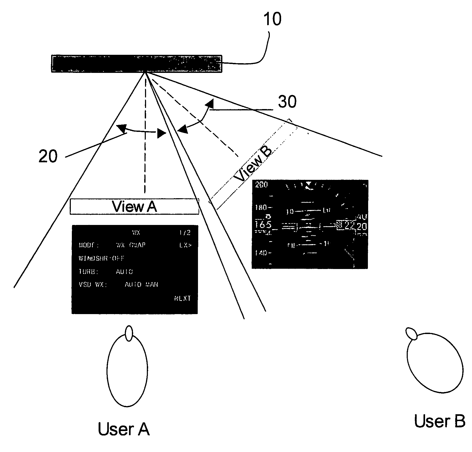
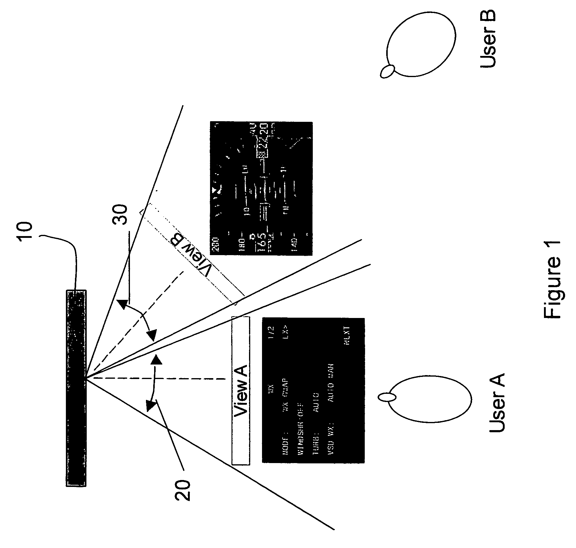
[0022]In accordance with embodiments of the invention, vehicle display systems and instrument panels may be configured with multi-view displays in order, for example, to maximize the limited space available to multi-crew member vehicles. These vehicles may include, but should not be limited to, tanks, armored vehicles, ships, submarines, aircraft, and spacecraft.

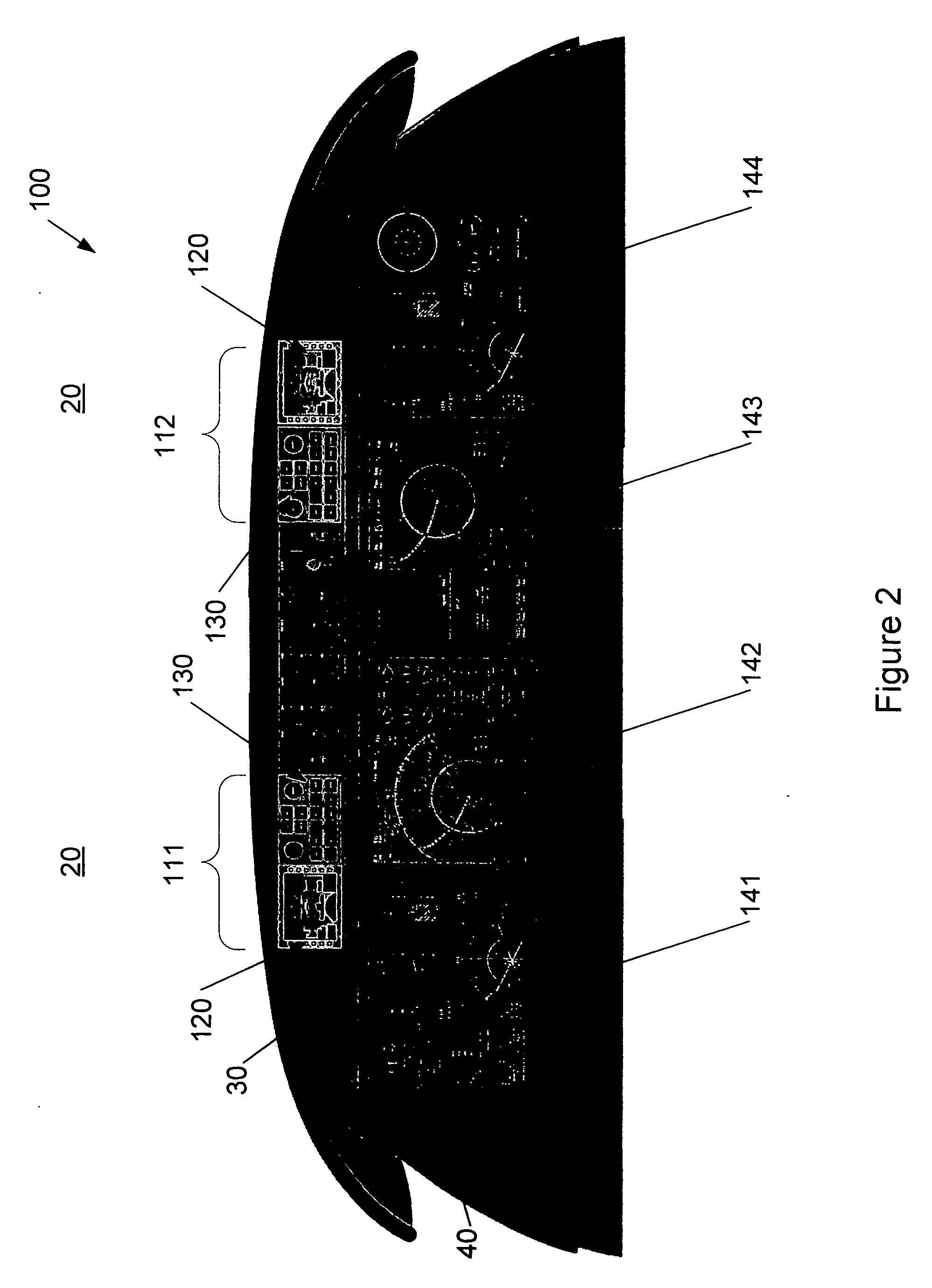
[0023]In an illustrative example of some embodiments of the invention, an aircraft instrument panel display may be configured to employ a multi-view display in order, for example, to maximize instrument panel real estate, reduce crew workload, minimize additional training, eliminate the addition of new op...


PUM


Abstract

Embodiments of the invention relate to a vehicle instrumentation systems and display systems employing multi-view displays in various land, water, air, and / or space vehicles. In one embodiment of the invention, an aircraft instrumentation system for a flight deck instrument panel includes at least one multi-view display configured to display at least two views, associating one view with a first crew member and the other view with a second crew member. In another embodiment of the invention, a standby instrument may be displayed on each of two multi-view displays such that a standby instrument is visible to each crew member at all times during aircraft operation.

Description

[0001]This application claims priority to co-pending U.S. Provisional Patent Application 60 / 817,748, filed Jun. 30, 2006, and entitled “Aircraft Systems Using Multi-View Displays,” which is hereby incorporated by reference in its entirety.FIELD OF THE INVENTION[0002]This invention relates to vehicle display systems and, more particularly, to instrument panels or control display systems employing multi-view displays.BACKGROUND OF THE INVENTION[0003]Control systems and instrumentation panels for modern vehicles, such as, for example, armored vehicles, tanks, aircraft, and spacecraft, include advanced computer electronics and displays systems. Modern aircraft, for example, employ advanced instruments and display systems, often including large displays, measuring up to 14 inches by 10 inches (about 35.5 cm by about 25.4 cm). Further, many modern aircraft may use multiple large displays, in some cases numbering four or more displays for a large passenger aircraft. As such, flight deck sp...

Claims


Application Information

Patent Timeline
Patent Type & Authority Applications(United States)
IPC IPC(8): G09G5/00H04N13/349
CPCG01C23/00H04N13/0445H04N13/0402H04N13/302H04N13/349
Inventor KRATCHOUNOVA, DANIELALANDERS, STEPHEN F.NEWTON, RONALD ALBERT
Owner GENERAL DYNAMICS GULFSTREAM AEROSPACE
Why Eureka
Try Eureka