
Layout structure of power steering system for vehicle

a technology of power steering and layout structure, which is applied in the direction of power steering, fluid steering, vehicle components, etc., can solve the problems of increasing cost, and achieve the effect of increasing strength and stiffness

Active Publication Date: 2006-07-18
HONDA MOTOR CO LTD
View PDF3 Cites 25 Cited by
  • Summary
  • Abstract
  • Description
  • Claims
  • Application Information

AI Technical Summary

Benefits of technology

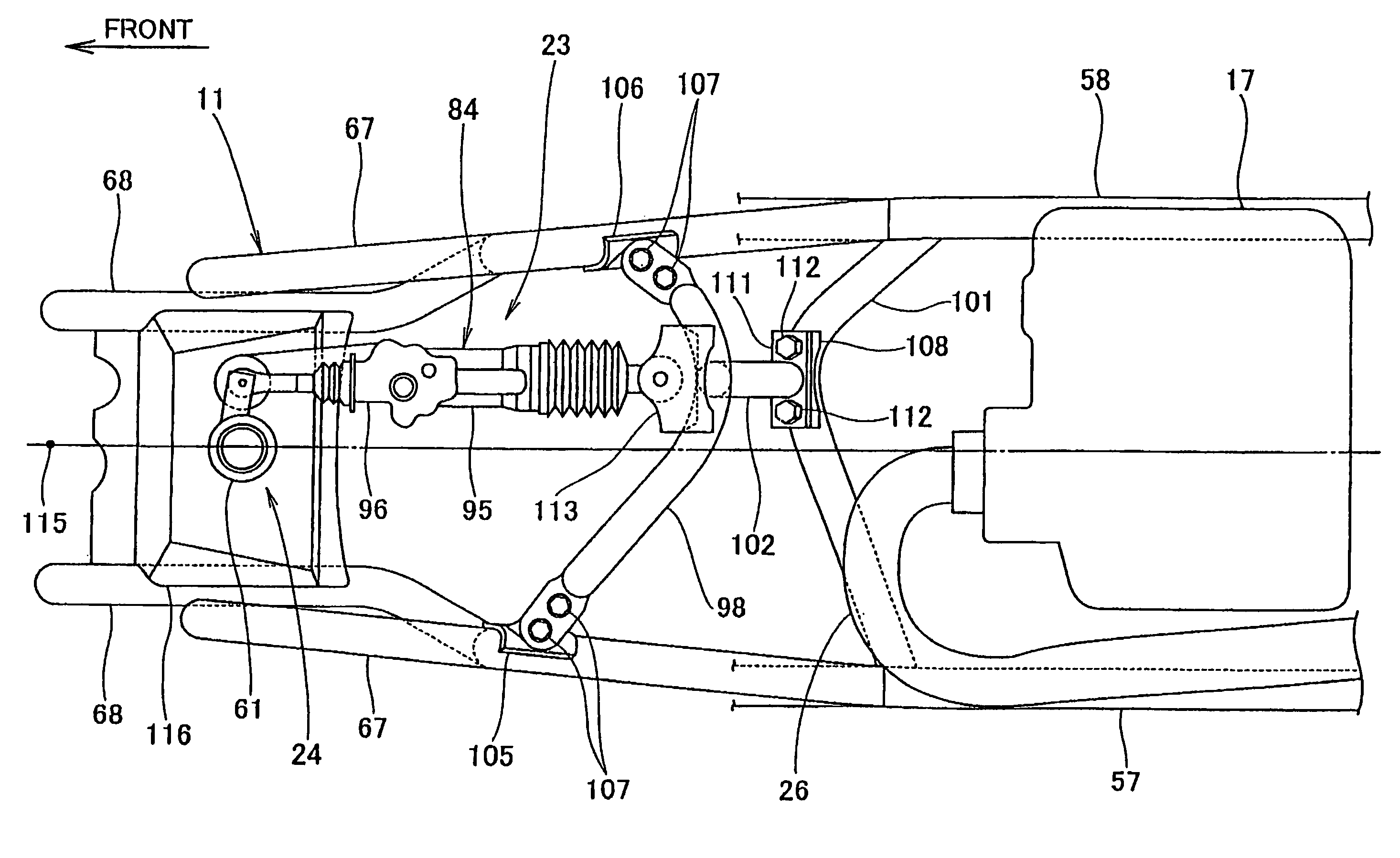
The present invention provides a power steering system for a vehicle that allows for more design freedom and arrangement of auxiliary parts around the power assisting actuator without the need for special reinforcement structures or increased strength and stiffness in the body frame. The actuator is installed to a cross pipe on the body frame and the reaction force generated by the actuator is supported by the cross pipe. The actuator, hydraulic piping, and oil pump are kept apart from the exhaust pipe, which reduces the impact of beat from the exhaust pipe and eliminates the need for heat countermeasures. The actuator and hydraulic piping are also installed on the opposite side of the engine with respect to the center line of the chassis, which further increases the degrees of freedom in design.

Problems solved by technology

Thus, the sectional area is made larger and a reinforcement must be made in order to prevent its deflection from becoming great, resulting in an increase in cost.

Method used


Image

  • Layout structure of power steering system for vehicle
  • Layout structure of power steering system for vehicle
  • Layout structure of power steering system for vehicle

Examples


Embodiment Construction

[0035]Hereinafter, with reference to the accompanying drawings, the description will be made of the best mode for carrying out the invention.

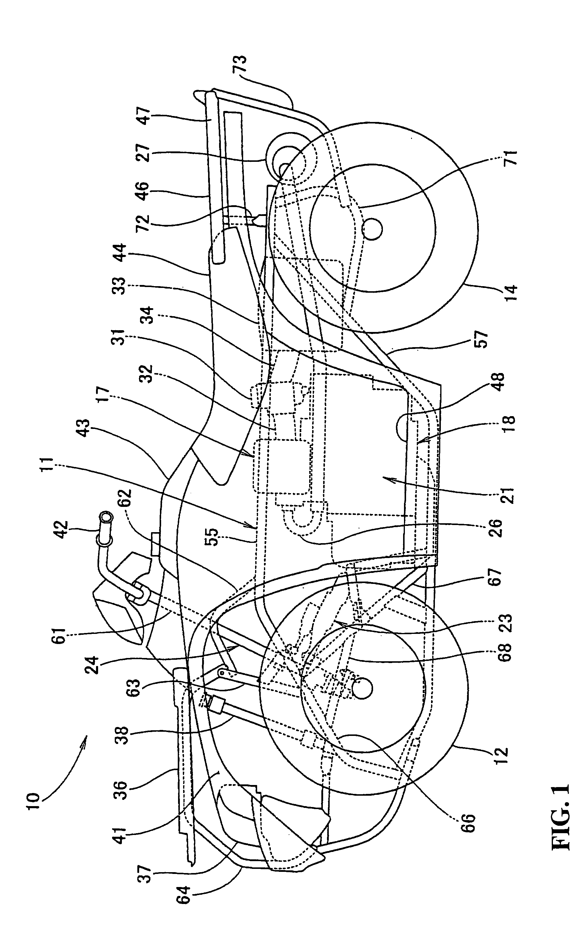
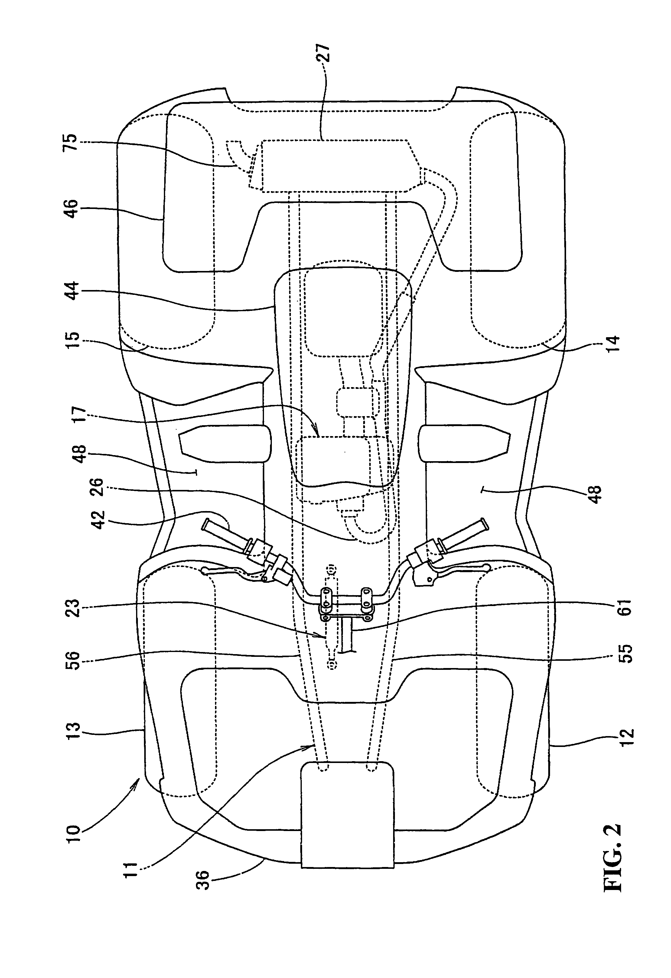
[0036]FIG. 1 is a side view of an uneven land driving vehicle 10, such as a four-wheel-drive vehicle, having a front part of the body frame 11 with front wheels 12, 13 having a broad width therebetween (only a reference numeral 12 on this side is shown) are installed via a suspension arm (not shown). In the rear of the body frame 11, rear wheels 14, 15 with a broad width therebetween are installed via a suspension arm (not shown). In the central part of the body frame 11, a power unit 21 consisting of an engine 17 and a transmission 18 is installed with the power unit 21 driving the front wheels 12, 13 and the rear wheels 14, 15 respectively.

[0037]The front wheels 12, 13 are steered by a steering system 24 to which a power steering system 23 has been attached.

[0038]The engine 17 has an exhaust piping 26 for extending from the front part thereof...


PUM


Abstract

The degrees of freedom in the design of a layout structure of a power steering system for a vehicle are increased so that the auxiliary parts can be arranged around the power assisting actuator without the need for a special increase in the strength and in the stiffness of a body frame for installing the power steering system. The front wheels are steered by a power steering system supported by the body frame wherein the power steering system is provided with an actuator for assisting a steering force. One end of the actuator is installed to a first cross pipe laid over the left and right portions of the body frame. The arrangement is such so that a longitudinal direction of the actuator runs substantially in parallel with a center line of a chassis extending in a back-and-forth direction of the vehicle body.

Description

CROSS-REFERENCE TO RELATED APPLICATIONS[0001]The present application claims priority under 35 USC 119 to Japanese Patent Application No. 2003-339849 filed on Sep. 30, 2003 the entire contents of which are hereby incorporated by reference.BACKGROUND OF THE INVENTION[0002]1. Field of the Invention[0003]The present invention relates to layout structure of a power steering system for a vehicle, and more particularly to layout structure of an actuator.[0004]2. Description of Background Art[0005]A conventional layout structure of a power steering system for a vehicle is known wherein the power steering system is arranged in a front part of a body frame by coupling the front end of an actuator for constituting the power steering system to a steering shaft and installing the rear end of the actuator to a component part of the body frame. See, for example, Japanese Patent Laid-Open No. 2617208, FIGS. 1 and 3.[0006]FIG. 10 of the drawings corresponds to FIG. 3 of Japanese Patent Laid-Open No....

Claims


Application Information

Patent Timeline
Patent Type & Authority Patents(United States)
IPC IPC(8): B62D5/06B62D5/087B62K5/08B62D5/12B62K5/00B62K5/01
CPCB62D5/087B62D5/12Y10S180/908
Inventor HASEGAWA, YOSUKE
Owner HONDA MOTOR CO LTD
Learn More