Tuning device and method for musical instrument

a technology of tuning device and musical instrument, which is applied in the direction of identification means, instruments, measurement apparatus components, etc., can solve the problems of difficult use of the tuning device in which the meter section has been configured, difficulty in carrying out fine tuning under conditions in which the pitch of the input signal approaches the standard pitch, and difficulty in carrying out fine tuning. , to achieve the effect of reducing power consumption, reducing the occurrence of wiring failures, and improving usability

Inactive Publication Date: 2008-10-14
ROLAND CORP
View PDF9 Cites 0 Cited by
  • Summary
  • Abstract
  • Description
  • Claims
  • Application Information

AI Technical Summary

Benefits of technology

[0020]Therefore, since neither a spring nor an electromagnet is used for driving the indicator, there is the advantageous result that it is possible to economically reduce the display error that is produced, which has been a problem with the mechanical meters of the past and together with this, the effective life can be improved. In addition, since it is possible to reduce the variations between the individual meters by using an ultrasonic motor, it is not necessary to install a fine adjustment capability, and there is the advantageous result that the processes at the time of manufacture can be simplified. Furthermore, because the structure of an ultrasonic motor is, in general, simple, there is the advantageous result that it is possible to design for the miniaturization of the tuning device overall.
[0026]Also, since the amount of movement of the indicator is limited by a stopper section, it is possible to limit the amount of movement of the indicator to the region of the deviation that should be displayed. Therefore, there is the advantageous result that in those cases where the deviation is displayed by an indication using the indicator, it is possible for the indicator to be moved within the region of the deviation that should be displayed.

Problems solved by technology

Because the display of the deviation is in steps, in other words, not continuous, however, there is a weakness that fine tuning under conditions in which the pitch of the input signal approaches the standard pitch is difficult to carry out and the device is difficult to use.
In that regard, a tuning device in which the meter section has been configured with a mechanical meter such as, for example, that cited in Japanese Patent Publication No. 3,231,362 is expensive, but since the display of the deviation changes continuously, tuning is carried out easily and this meter section is in high demand.
However, because the driving of the indicator is carried out by the repulsive force of a spring and the magnetic force of an electromagnet, there have been various kinds of problems that accompany the use of the spring and the electromagnet (coil and magnet) with the mechanical meter.
Specifically, one problem that arises is that because over time a deterioration of the spring is produced and as a matter of course, a chronological display error is generated and compared to a meter that uses LEDs or LCDs, the life of the mechanical meter is short.
In addition, other problem areas include the fact that since an electromagnet is used, the meter is likely to be affected by the magnetic forces in the surroundings and, for example, in the vicinity of devices that generate magnetic forces such as the speaker of a guitar amplifier and or a guitar pickup.
As such, accurate tuning cannot be carried out and the places that the device can be used are limited.
Also, since the movement of the indicator, which has a weak retention torque, is affected by the force of gravity, there have been problems such as the fact that items that are to be placed vertically cannot be placed horizontally and both the direction of placement and the angle of placement are limited.
In addition, because the wiring to the electromagnet with which the indicator is driven is placed in the vicinity of the indicator, there has been the problem that failures are likely to occur in the wiring together with the driving of the indicator.
Also, since an electromagnet is used to drive the indicator, power consumption is great and, as a result, there has been the problem that in those cases where a mechanical meter is employed in a tuning device for portable use.
In addition, there have been problems such as the fact that since variations are likely to occur between individual meters and in order to absorb these variations, the use of a semi-fixed resistor and the like is provided capable of performing fine adjustments.
Also, it is necessary to carry out the adjustments at the time of shipping, making the processes at the time of manufacture complicated.
Furthermore, since a coil and a magnet are installed as items that are fundamental to the spring and the electromagnet, there has been the problem that there is a limit to miniaturization of the mechanical meter and to making the mechanical meter thin.

Method used


Image

  • Tuning device and method for musical instrument
  • Tuning device and method for musical instrument
  • Tuning device and method for musical instrument

Examples


Embodiment Construction

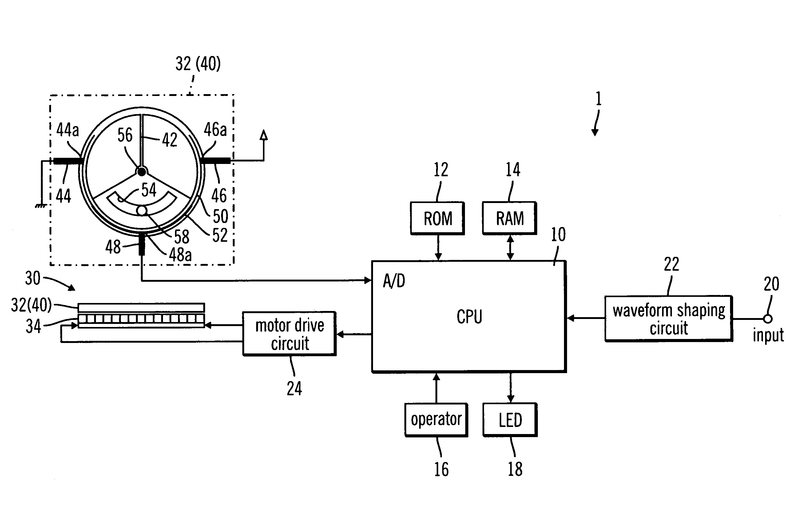
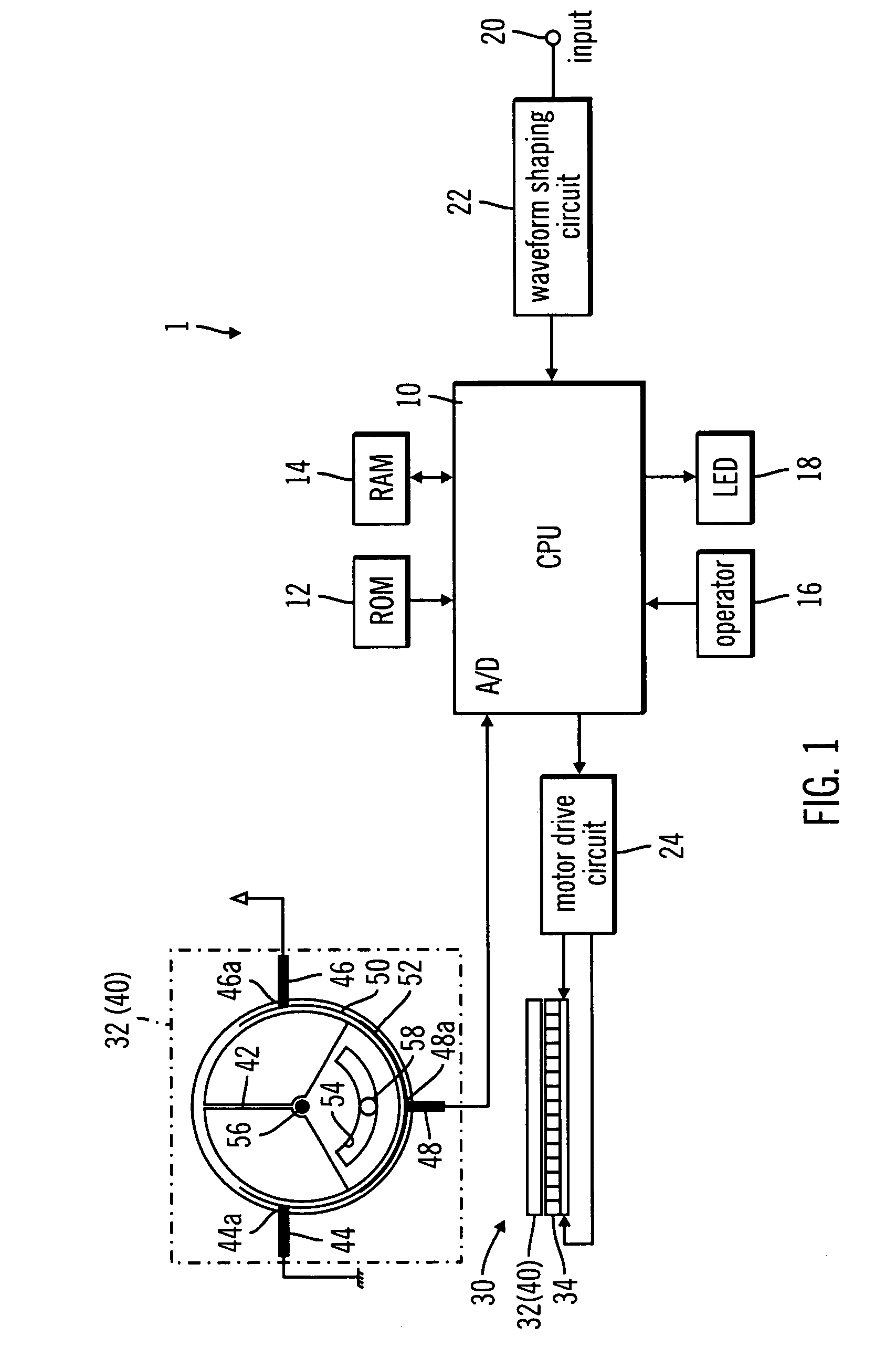
[0030]An explanation will be given below regarding an example embodiment of the present invention while referring to the attached drawings. FIG. 1 is a block diagram that shows the configuration of the tuning device 1, which is one example embodiment of the present invention. As shown in FIG. 1, the tuning device 1 is furnished primarily with a signal input terminal 20, a waveform shaping circuit 22, which is an analog circuit that amplifies the input guitar signal that has been input from a guitar (not shown in the drawing) through the signal input terminal 20 (hereinafter, referred to simply as the “input signal”) and shapes the waveform into a square wave, a (CPU) 10, a (ROM) 12, a (RAM) 14, operators 16, LEDs 18, an ultrasonic motor 30 that has a meter section 40, and a motor drive circuit 24, which is a circuit that produces the drive signal for driving the ultrasonic motor 30.

[0031]The CPU 10 is a central processing unit that controls the entire tuning device 1 and is furnishe...


PUM


Abstract

A tuning device includes a pitch extraction device with which the pitch of an input signal is extracted and a deviation detection device with which the deviation of the pitch that has been extracted by the pitch extraction device from a standard pitch is detected. The deviation that has been detected by the deviation detection device is displayed by an indicator of a mechanical meter. The tuning device also includes an ultrasonic motor that drives the indicator. A controller drives the ultrasonic motor in conformance with the deviation that has been detected by the deviation detection device. The controller, by driving the indicator using the ultrasonic motor, arranges the indicator in the standard position in those cases where the deviation that has been detected by the deviation detection device is zero, and moves the indicator up to a position in the positive direction that corresponds to the deviation in those cases where the deviation is a positive value and moves the indicator up to a position in the negative direction that corresponds to the deviation in those cases where the deviation is a negative value.

Description

CROSS-REFERENCE TO RELATED PATENT APPLICATIONS[0001]Japan Priority Application 2005-121989, filed Apr. 20, 2005 including the specification, drawings, claims and abstract, is incorporated herein by reference in its entirety.BACKGROUND OF THE INVENTION[0002]1. Field of the Invention[0003]Embodiments of the present invention relate to a tuning device and method with which the tuning of a musical instrument such as a guitar or a wind instrument and the like is carried out and, in particular, to a tuning device that has a mechanical meter.[0004]2. Related Art[0005]In conventional tuning devices for musical instruments, the meter section which shows the deviation of the pitch of an input signal from a standard pitch, typically includes display meters. Such meters carry out the display of the deviation by a display using light emitting diode (LED)s or liquid crystal displays (LCD)s as well as mechanical meters that carry out the display of the deviation using the movement of an indicator ...

Claims


Application Information

Patent Timeline
Patent Type & Authority Patents(United States)
IPC IPC(8): G10G7/02
CPCG10G7/02Y10S84/18
Inventor YAMADA, YASUYUKI
Owner ROLAND CORP
Why Eureka
Try Eureka