Supercharge Your Innovation With Domain-Expert AI Agents!

Automatic gain control apparatus

a gain control and automatic technology, applied in the direction of gain control, digital transmission, transmission, etc., can solve the problems of reducing the overall performance of the receiver, the limitation of the lpf's bandwidth, and the performance of the receiver may be unexpectedly damaged, so as to simplify the system configuration

Inactive Publication Date: 2008-10-14
ELECTRONICS & TELECOMM RES INST
View PDF14 Cites 7 Cited by
  • Summary
  • Abstract
  • Description
  • Claims
  • Application Information

AI Technical Summary

Problems solved by technology

Typically, an automatic gain controller (AGC) for use in wired / wireless communication guarantees stable operations of a variety of devices contained in a reception end, for example, a timing recovery device, a carrier recovery device, and an equalizer, etc., and maintains the magnitude of a reception signal at a desired level, resulting in reduction of overall performance of a receiver.
In this case, provided that the magnitude of input signals is contained in a prescribed dynamic range during which a plurality of blocks contained in the receiver can be operated, overall performances of the receiver may be unexpectedly damaged.
However, provided that the bandwidth of the LPF 122 is excessively increased, a noise component unexpectedly occurs, such that a correct magnitude of the output signal S21 cannot be detected, resulting in the creation of an error associated with the gain control signal S22.
Due to the above-described problems, the conventional automatic gain control device has a limitation in increasing the LPF's bandwidth to establish the above high-speed gain control operation, such that it is difficult to acquire a sufficiently-high gain control speed requested by a high-speed data communication system employing burst signals.
Furthermore, the conventional automatic gain control device has been adapted to process analog signals, resulting in a complicated gain control process and a greater error rate.

Method used


Image

  • Automatic gain control apparatus
  • Automatic gain control apparatus
  • Automatic gain control apparatus

Examples


Embodiment Construction

[0042]Now, preferred embodiments of the present invention will be described in detail with reference to the annexed drawings. In the drawings, the same or similar elements are denoted by the same reference numerals even though they are depicted in different drawings. In the following description, a detailed description of known functions and configurations incorporated herein will be omitted when it may make the subject matter of the present invention rather unclear.

[0043]Operations and detailed configuration of the automatic gain control device of the present invention will hereinafter be described in detail.

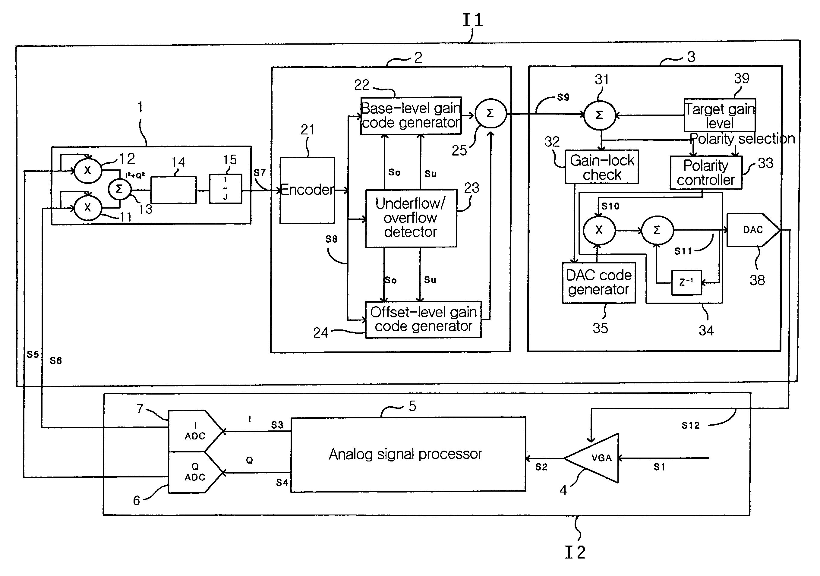
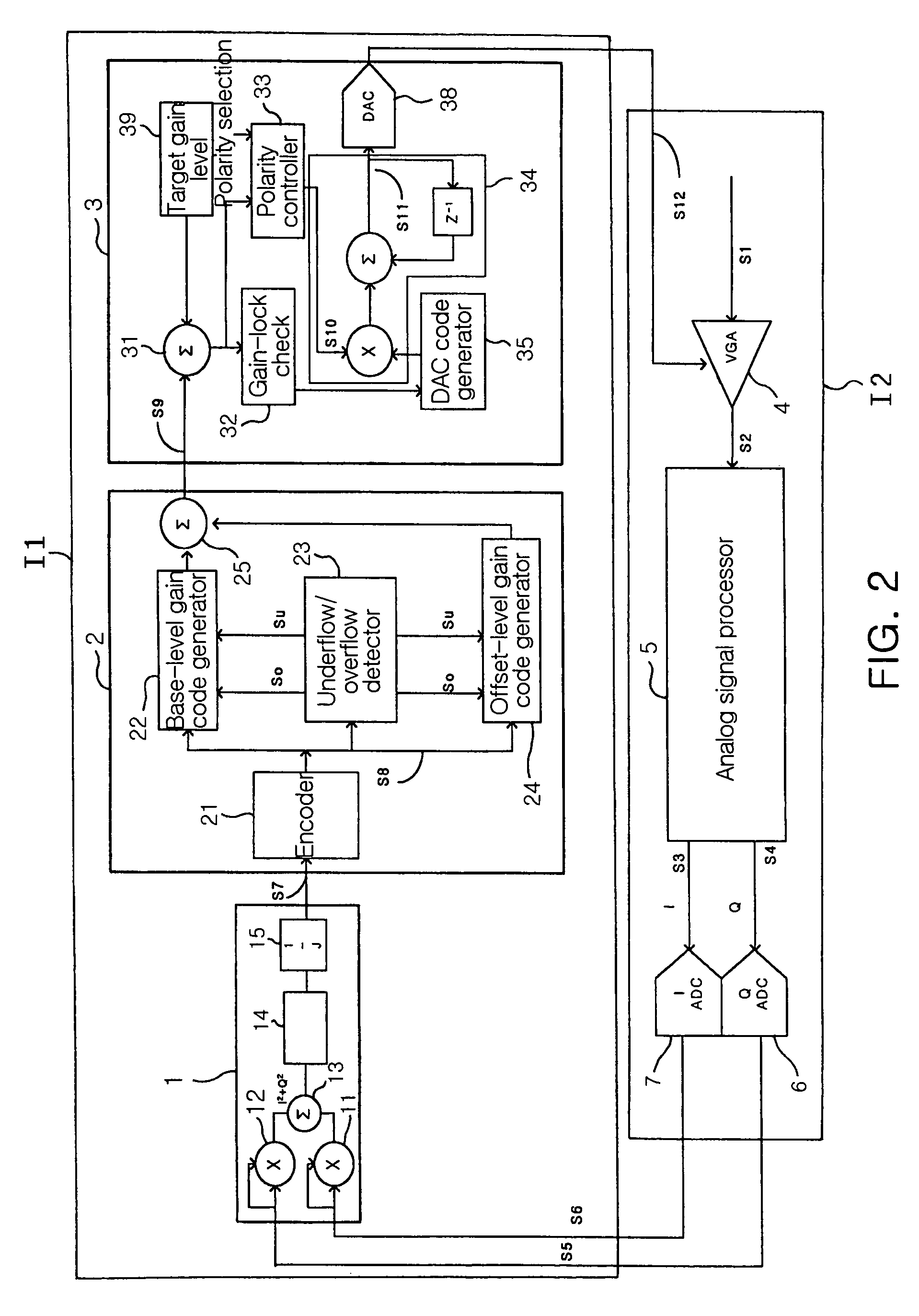
[0044]FIG. 2 is a block diagram illustrating an overall configuration of an automatic gain control apparatus in accordance with the present invention. Referring to FIG. 2, a reference character “I1” is indicative of an automatic gain controller for calculating a necessary gain associated with an input signal S1 received by wire or wirelessly to generate a gain control signal co...


PUM


Abstract

The present invention relates an automatic gain control device, which performs a high-speed gain control operation in high-speed data communication using burst signals, generates a gain code without using a memory or storage device to simplify a system configuration, and establishes a correct gain control operation. The automatic gain control apparatus includes a power detector for calculating a mean power of the output signal of the variable gain amplifier; a gain code generator for receiving a mean power from the power detector, and generating a gain code corresponding to the received mean power; and a voltage generator for calculating a difference between the gain code and a target gain code associated with the output signal of the variable gain amplifier to detect an error code, and generating a gain control voltage for compensating for the difference between the two gain codes on the basis of the detected error code.

Description

BACKGROUND OF THE INVENTION[0001]1. Field of the Invention[0002]The present invention relates to an automatic gain control apparatus, and more particularly to an automatic gain control apparatus for controlling the magnitude of a reception signal for use in wired / wireless communication such that it can optimally control a plurality of devices contained in a receiver.[0003]2. Description of the Related Art[0004]Typically, an automatic gain controller (AGC) for use in wired / wireless communication guarantees stable operations of a variety of devices contained in a reception end, for example, a timing recovery device, a carrier recovery device, and an equalizer, etc., and maintains the magnitude of a reception signal at a desired level, resulting in reduction of overall performance of a receiver. The magnitude of input signals of the reception end for use in general wired / wireless communication varies with transmission and channel conditions. In this case, provided that the magnitude of...

Claims


Application Information

Patent Timeline
Patent Type & Authority Patents(United States)
IPC IPC(8): H04L27/08H03G3/30H03G3/20H04B1/16H04L27/38
CPCH03G3/3036H04L27/3809H03G3/20
Inventor KANG, HUN SIKHWANG, DAE HWANKIM, JI EUNBAEK, JEIN
Owner ELECTRONICS & TELECOMM RES INST
Features
  • R&D
  • Intellectual Property
  • Life Sciences
  • Materials
  • Tech Scout
  • Unparalleled Data Quality
  • Higher Quality Content
  • 60% Fewer Hallucinations
Learn More