Wireless camera flash synchronizer system and method

a synchronizer and camera technology, applied in the field of camera flash synchronization, can solve the problems of increasing power consumption and adding to the cost of the synchronizer

Inactive Publication Date: 2008-10-14
LAB PARTNERS ASSOC INC
View PDF5 Cites 40 Cited by
  • Summary
  • Abstract
  • Description
  • Claims
  • Application Information

AI Technical Summary

Problems solved by technology

Having separate radio circuits can add to the cost of the synchronizer and increase power consumption.

Method used


Image

  • Wireless camera flash synchronizer system and method
  • Wireless camera flash synchronizer system and method
  • Wireless camera flash synchronizer system and method

Examples


Embodiment Construction

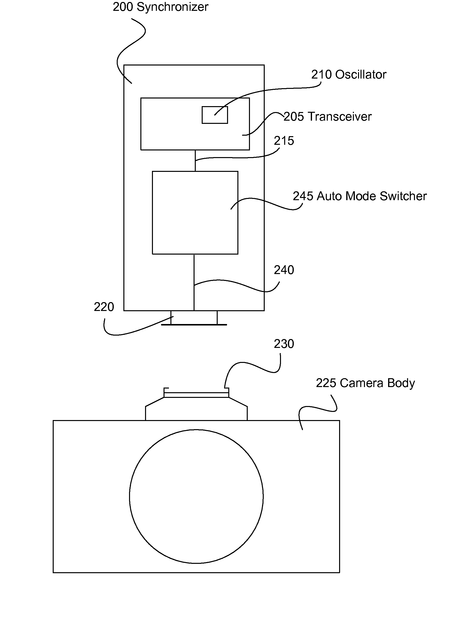
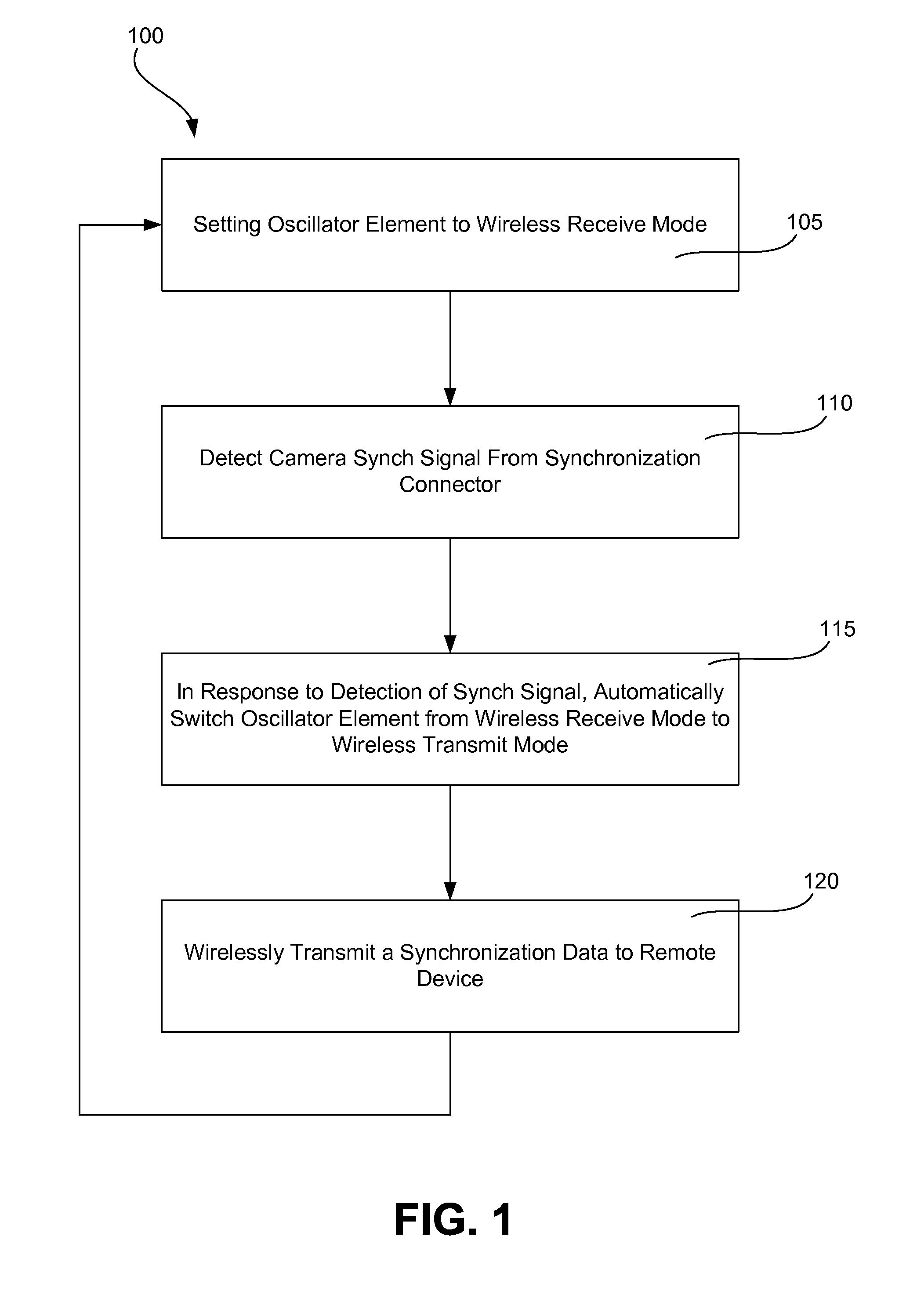
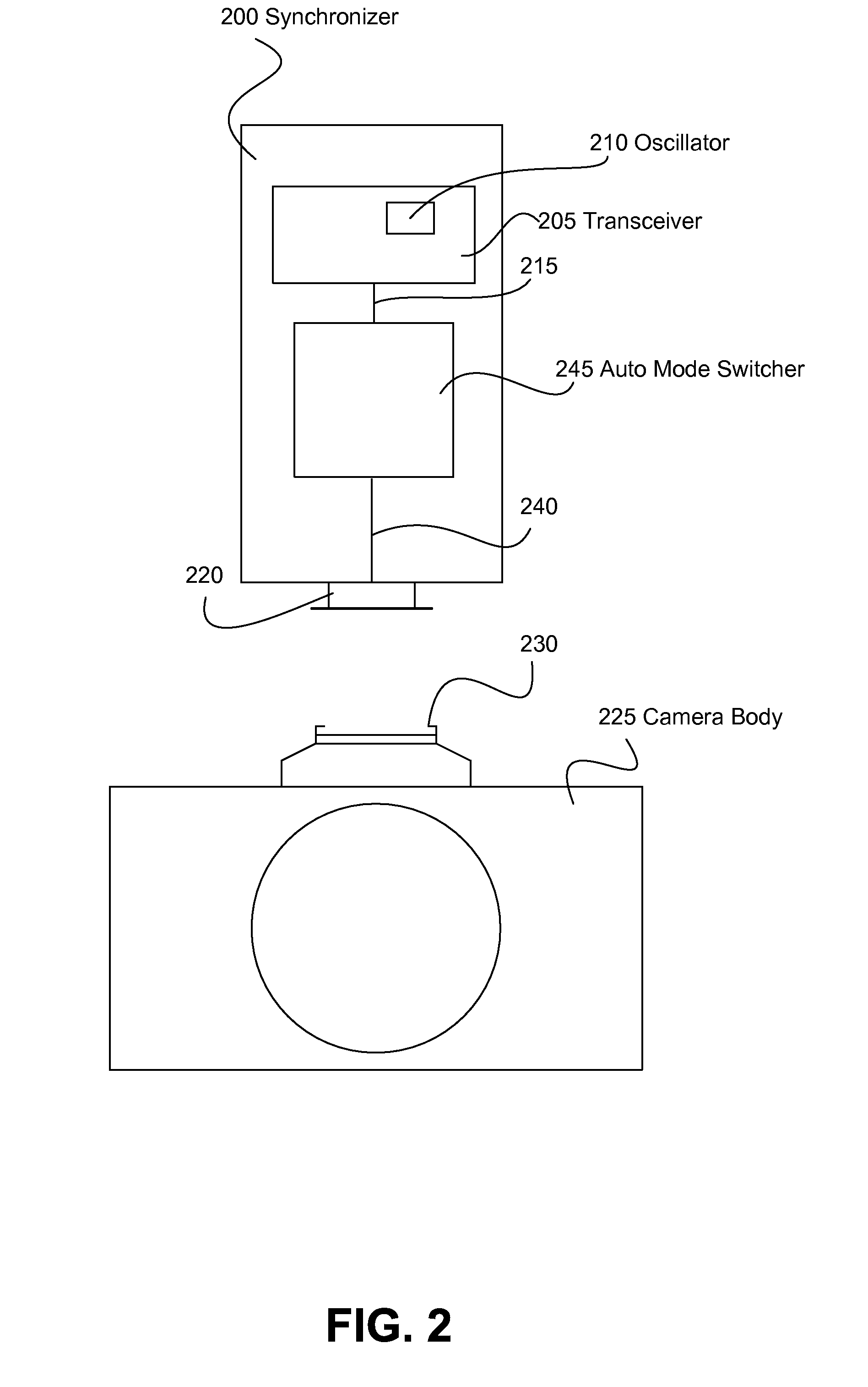
[0011]A single oscillator system and method is provided that automatically switches from a receive mode to a transmit mode upon the detection of a synchronization (synch) signal of a camera body.

[0012]FIG. 1 illustrates one embodiment of a method 100 of wirelessly communicating a camera synchronization to a remote device from a camera body. At step 105, an oscillator element of a wireless camera flash synchronizer is set to a receive mode. Various embodiments of a wireless camera flash synchronizer are set forth below (e.g., wireless camera flash synchronizer 200, 300 of FIGS. 2 and 3, respectively). A wireless camera flash synchronizer may be physically connected to the camera body in a variety of ways. In one example, a wireless camera flash synchronizer may be connected to a synchronization signal connector of the camera body. Examples of a synchronization signal connector include, but are not limited to, a camera hotshoe, a camera PC connector, a direct wiring to the internal ci...


PUM


Abstract

A single oscillator synchronizer system and method that automatically switches from a wireless receive mode of the oscillator to a wireless transmit mode of the oscillator upon the detection of a synchronization (synch) signal of a camera body. In one example, a method of wirelessly communicating a camera synchronization from a camera body to a remote device with a wireless camera flash synchronizer connected to a synchronization connector of the camera body, the wireless camera flash synchronizer including a transceiver having an oscillator element with a wireless receive mode and a wireless transmit mode, the oscillator element configured to be in only one of the wireless receive mode and wireless transmit mode at a time is provided. In another example, a wireless camera flash synchronizer that automatically switches from a wireless receive mode to a wireless transmit mode upon detection of a synch signal of a camera body is provided.

Description

RELATED APPLICATION DATA[0001]This application claims the benefit of priority of U.S. Provisional Patent Application Ser. No. 60 / 790,355, filed Apr. 7, 2006, and titled “Wireless Camera Flash Synchronizer System and Method, which is incorporated by reference herein in its entirety.FIELD OF THE INVENTION[0002]The present invention generally relates to the field of camera flash synchronization. In particular, the present invention is directed to a wireless camera flash synchronizer system and method.BACKGROUND[0003]Synchronization of a camera flash to the acquisition of an image can be done wirelessly between a camera and a remote flash device or other device requiring synchronization. Typically, prior synchronizers require a user to manually switch the device from a receive mode to a transmit mode utilizing a physical switch on the device. The speed demands imposed by cameras require near instantaneous transmission of a synchronization command to the remote device in order for the re...

Claims


Application Information

Patent Timeline
Patent Type & Authority Patents(United States)
IPC IPC(8): G03B17/00H04N5/232
CPCG03B15/02G03B17/00
Inventor CLARK, JAMES E.
Owner LAB PARTNERS ASSOC INC
Why Eureka
Try Eureka