Screwdriver bit

a screwdriver and bit technology, applied in the field of screwdriver bits, can solve problems such as potential user hazards, and achieve the effect of improving use safety

Active Publication Date: 2008-10-21
COMPASS
View PDF3 Cites 44 Cited by
  • Summary
  • Abstract
  • Description
  • Claims
  • Application Information

AI Technical Summary

Benefits of technology

[0006]The present invention solves this need and other problems in the field of screwdriver bits by providing, in a preferred form, a screwdriver bit including a shank adapted to releasably couple with a tool for rotating the shank. A first engaging portion extends from one of two ends of the shank and includes a first insertion section adapted for coupling with a fastener. A reduced, threaded section is formed between one of the ends of the shank and the first insertion section of the first engaging portion. The reduced, threaded section includes an outer diameter smaller than that of the ends of the shank and an outer threading. The outer threading of the reduced, threaded section provides uniform stress distribution during torque transmission to enhance use safety.

Problems solved by technology

Breakage of the bit 12 in the transition section 125 may occur during operation, resulting in potential a hazard to the user.

Method used


Image

  • Screwdriver bit
  • Screwdriver bit
  • Screwdriver bit

Examples


first embodiment

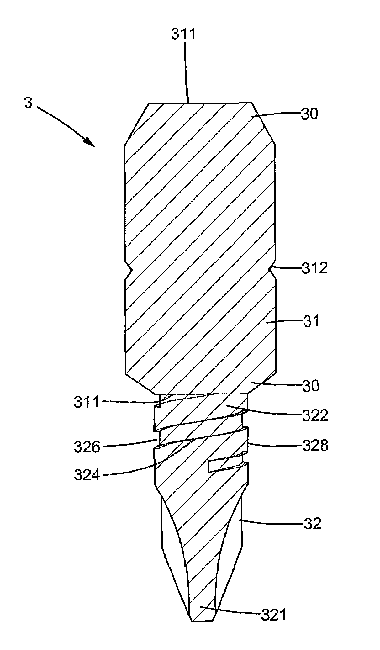
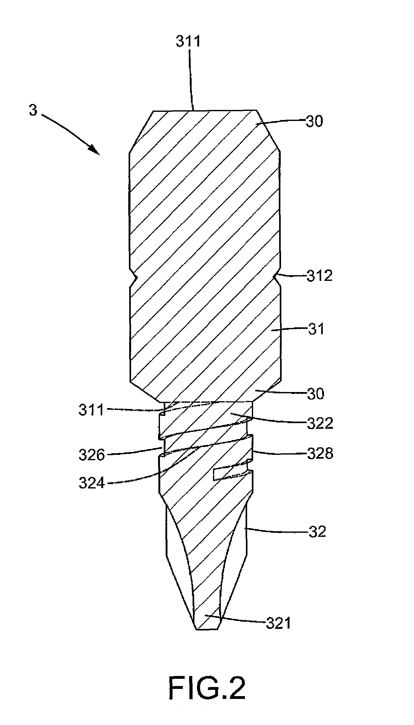
[0021]A screwdriver bit of according to the preferred teachings of the present invention is shown in FIGS. 2-4 of the drawings and generally designated 3. The screwdriver bit 3 is generally integrally formed of metal and includes a shank 31 and an engaging portion 32 extending from an end face 311 of an end 30 of the shank 31. According to the preferred form, the shank 31 has hexagonal cross sections for releasable coupling with a socket 13 of a head 111 of a wrench handle 11 that can be operated to rotate the shank 31. The shank 31 further includes a plurality of recesses 312 in an outer periphery thereof for coupling with a retainer (not shown) in the socket 13, allowing the shank 31 to be securely retained in the socket 13. The shank 31 can be coupled with tools of any desired form as conventional including but not limited to of a commercially available type.

[0022]The engaging portion 32 includes an insertion section 321 to be coupled with a groove 21 in a head of a fastener 2 su...

second embodiment

[0024]FIG. 5 shows a screwdriver bit 3 of a second embodiment according to the preferred teachings of the present invention. In the screwdriver bit 3 of FIG. 5, an engaging portion 32 extends from each of two ends 30 of the shank 31. According to the preferred form shown, each engaging portion 32 of FIG. 5 is identical to the engaging portion 32 of FIGS. 2-4. The outer threading 324 on the reduced, threaded section 328 of each engaging portion 32 of the screwdriver bit 3 of FIG. 5 provides the same advantages as those of the engaging portion 32 of the screwdriver bit 3 of FIGS. 2-4. Detailed descriptions of the engaging portions 32 of FIG. 5 are omitted to avoid redundancy.

third embodiment

[0025]FIGS. 6-7 show a screwdriver bit 3 of a third embodiment according to the preferred teachings of the present invention. The screwdriver bit 3 of FIGS. 6 and 7 is substantially the same as that of FIG. 5 except that the shank 31 of FIGS. 6 and 7 is longer for use with a power tool 4. Specifically, the shank 31 includes first and second ends 31a and 31b and two engaging portions 32 respectively extending outward from the first and second ends 31a and 31b. A reduced, threaded section 313 is interconnected between the first and second ends 31a and 31b. The reduced, threaded section 313 has an outer diameter smaller than that of each engaging portion 32 and smaller than that of the first and second ends 31a and 31b of the shank 31. Furthermore, the reduced, threaded section 313 includes an outer threading 314. Further, an engaging groove 316 is formed between each end 31a, 31b of the shank 31 and an adjacent engaging portion 32 for coupling with the power tool 4. By such an arrange...


PUM


Abstract

A screwdriver bit includes a shank for coupling with a tool for rotating the shank. An engaging portion extends from one of two ends of the shank and includes an insertion section for coupling with a fastener. A reduced, threaded section is formed between one of the ends of the shank and the insertion section of the engaging portion. The reduced, threaded section includes an outer diameter smaller than that of the ends of the shank and an outer threading. The outer threading of the reduced, threaded section provides uniform stress distribution during torque transmission.

Description

BACKGROUND OF THE INVENTION[0001]The present invention relates to a screwdriver bit and, more particularly, to a screwdriver bit releasably coupled with a screwdriver for driving screws or the like.[0002]Screwdriver bits releasably coupled with a screwdriver for driving screws or the like are well known and have various types such as rectilinear, cruciform, hexagonal, inner hexagonal, and ring shapes corresponding to various groove shapes in the screw heads.[0003]FIG. 1 of the drawings illustrates a typical screwdriver bit 12 including a shank 121 releasably coupled with a socket 13. The bit 12 further includes an end 122 having an insertion portion 123 with a shape corresponding to that of a groove 21 in a head of a screw 2. The socket 13 is attached to a head 111 on an end of a handle 11 of a wrench 1 or a power tool (not shown). Releasable coupling between the bit 12 and the socket 13 allows a user to select a proper bit according to the type and size of the groove of the screw t...

Claims


Application Information

Patent Timeline
Patent Type & Authority Patents(United States)
IPC IPC(8): B25B15/00
CPCB25B15/001
Inventor WANG, JUI-HSIAO
Owner COMPASS
Why Eureka
Try Eureka