
Sleeve-actuated umbrella

a technology of umbrellas and actuators, applied in the field of umbrellas, can solve the problems of difficult operation of patio umbrellas that are particularly large, inconvenient operation, and inability to meet the needs of use, and achieve the effect of convenient operation and low cos

Inactive Publication Date: 2008-10-21
WILSON ROBERT J
View PDF21 Cites 10 Cited by
  • Summary
  • Abstract
  • Description
  • Claims
  • Application Information

AI Technical Summary

Benefits of technology

[0006]It is an object of the present invention to provide an umbrella with an actuator that is relatively inexpensive and easy to operate.
[0010]Another object of some embodiments is to avoid weakening an umbrella's tubular mast with a long slot.
[0013]Another object of some embodiments is to provide an umbrella with a button-release sleeve that makes it easier to release the umbrella from its open position.

Problems solved by technology

Patio style umbrellas that are particularly large can be difficult to operate due to the substantial force needed to raise the relatively heavy canopy to an open position.
A crank and gear reduction mechanism can be used to reduce the force, but such manual mechanisms can be tedious to use due to the time it takes to crank the umbrella open and closed.
The cranking action can also apply an undesirable rotational moment on the umbrella's mast, wherein the rotational moment urges the canopy to twirl back and forth with each revolution of the crank.
The motorized mechanism, of course, requires a source of electrical power that, unfortunately, might not always be readily available.
This design, unfortunately, requires a long slot (item 22 of the '383 patent) in the umbrella's mast, and such a slot is not easily manufacturable by high production means.
Moreover, such a slot can weaken the mast.

Method used


Image

  • Sleeve-actuated umbrella
  • Sleeve-actuated umbrella
  • Sleeve-actuated umbrella

Examples


Embodiment Construction

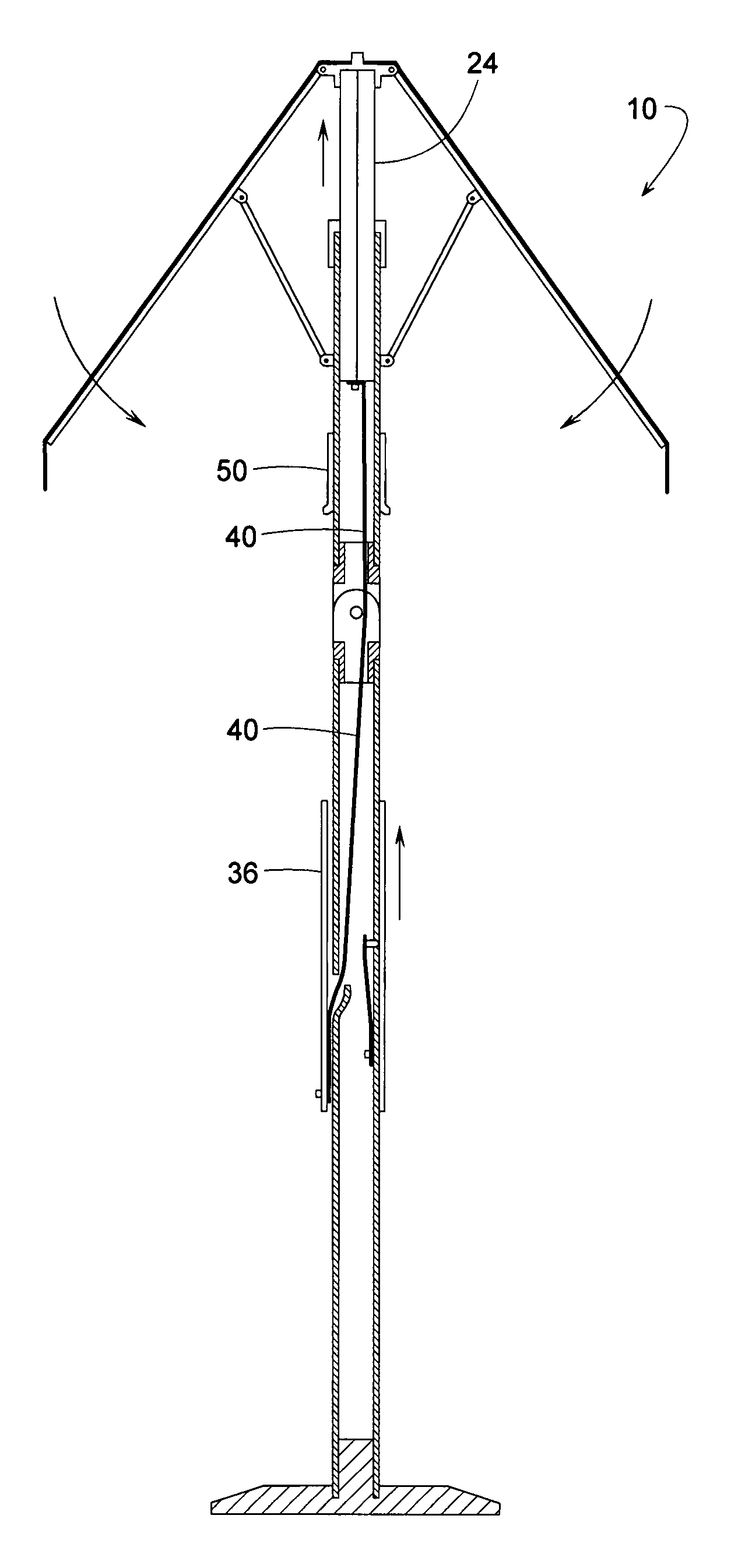
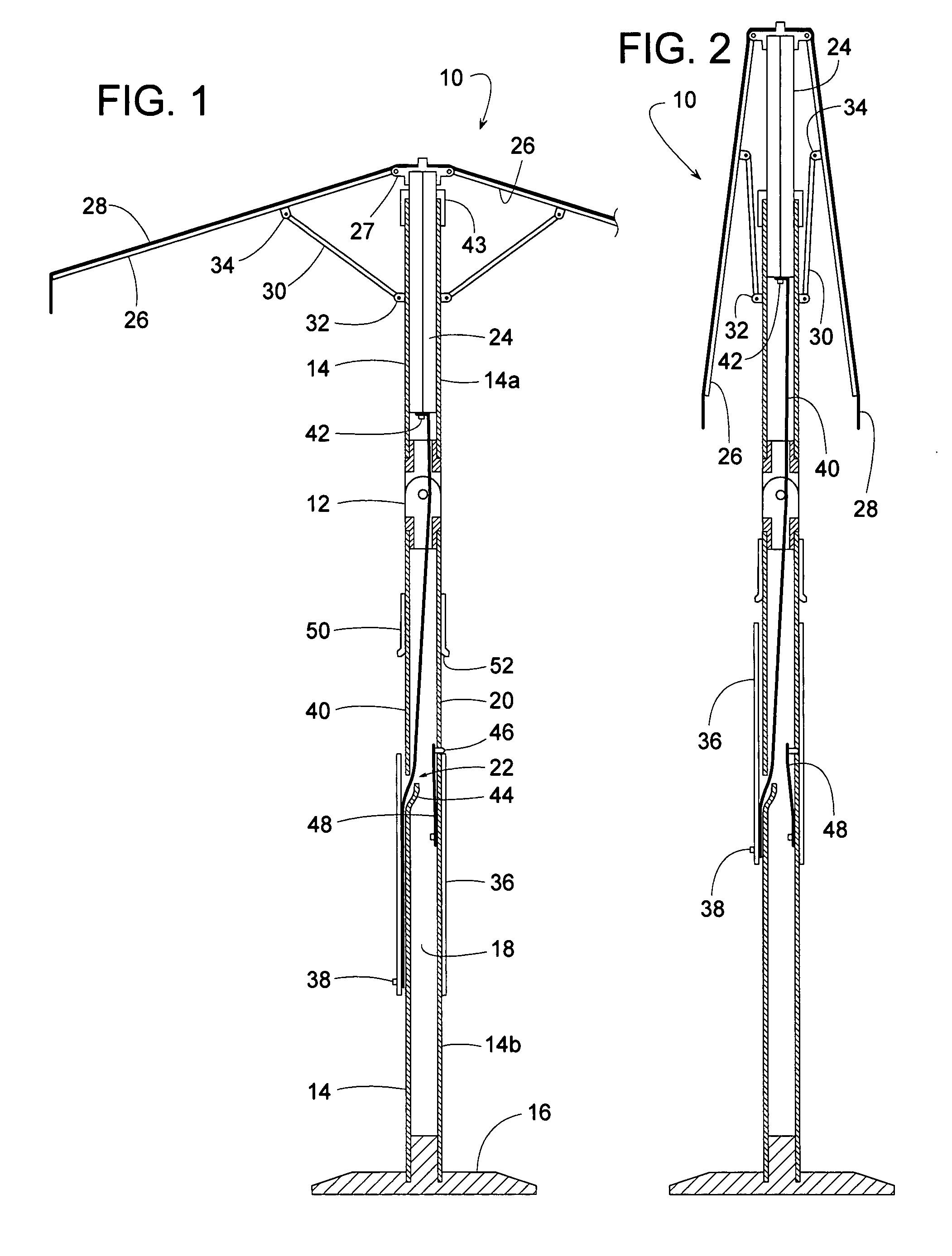
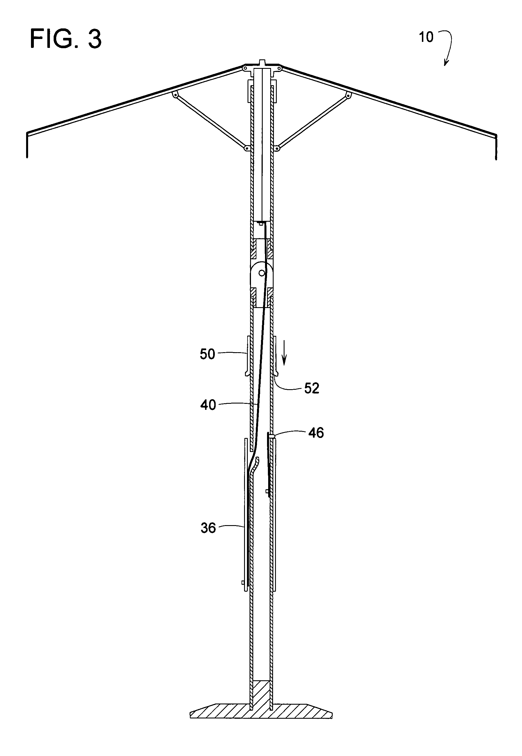
[0021]FIGS. 1-6 show an umbrella 10 that can be selectively configured to an open position (FIGS. 1, 3, 4 and 6) and a closed position (FIG. 2). FIG. 5 shows umbrella 10 partway between its fully open and closed positions. Although umbrella 10 is shown with a hinge 12 for tilting umbrella 10, as shown in FIG. 6, the subject invention also applies to non-tilting umbrellas without a hinge.

[0022]In some embodiments of the invention, umbrella 10 comprises a tubular mast 14 attached to a base 16. Mast 14 has an interior 18, an exterior 20, and a sidewall aperture 22. If umbrella 10 includes hinge 12, then mast 14 comprises an upper tube 14a and a lower tube 14b that are pivotally coupled to each other via hinge 12; otherwise, tubes 14a and 14b could be a unitary mast piece or rigidly interconnected. A shaft 24 telescopically coupled to mast 14 protrudes upward from upper tube 14a and can slide vertically relative to tube 14a. A series of ribs 26 supporting a fabric canopy 28 are pivotall...


PUM


Abstract

An umbrella has an intermediate point of equilibrium between its fully open and closed positions, which reduces the peak force required to move the umbrella in either direction. To actuate the umbrella, a resiliently flexible steel band is able to not only carry tension to pull the umbrella open, but the band also has sufficient rigidity to operate in compression to push the umbrella closed. The band's flexibility allows it to feed through a small sidewall hole in the mast as well as snake through a hinge on an umbrella mast that can tilt. Manually sliding an actuator sleeve upward closes the umbrella. Sliding the sleeve down opens the umbrella. Although lifting to close and lowering to open may seem counterintuitive at first, such action greatly reduces the maximum force required to operate the umbrella.

Description

FIELD OF THE INVENTION[0001]The subject invention generally pertains to umbrellas more specifically to an actuator for an umbrella.BACKGROUND OF RELATED ART[0002]Patio style umbrellas that are particularly large can be difficult to operate due to the substantial force needed to raise the relatively heavy canopy to an open position. A crank and gear reduction mechanism can be used to reduce the force, but such manual mechanisms can be tedious to use due to the time it takes to crank the umbrella open and closed. The cranking action can also apply an undesirable rotational moment on the umbrella's mast, wherein the rotational moment urges the canopy to twirl back and forth with each revolution of the crank.[0003]As an alternative, U.S. Pat. No. 6,058,951 discloses a motor powered umbrella where a motorized mechanism pulls on a set of spokes or linkage that lifts the canopy to its open, raised position. As explained in column 3, lines 46-48 of the '951 patent, the weight of the canopy ...

Claims


Application Information

Patent Timeline
Patent Type & Authority Patents(United States)
IPC IPC(8): A45B25/14A45B17/00
CPCA45B25/14A45B2023/0012
Inventor WILSON, ROBERT J.
Owner WILSON ROBERT J
Learn More