Compound aircraft control system and method

a control system and aircraft technology, applied in the direction of vehicle position/course/altitude control, process and machine control, instruments, etc., can solve the problems of low control complexity of compound aircraft, pilots of conventional helicopters having few control options, and no compound helicopters have been placed in regular operation in commercial or military fleets. , to achieve the effect of reducing lifecycle costs, reducing vibration, and increasing performance and speed

Active Publication Date: 2008-10-21
PIASECKI AIRCRAFT CORP
View PDF21 Cites 79 Cited by
  • Summary
  • Abstract
  • Description
  • Claims
  • Application Information

AI Technical Summary

Benefits of technology

[0018]The Invention is a control system for a compound aircraft. A user selects an overall objective for the control system, such as reducing vibration, increasing performance and speed, reducing lifecycle costs, reducing loading of one or more components, reducing fuel consumption, or any combination of these objectives or of any other desired objectives. The overall objective is pre-selected from among a plurality of overall objectives by the pilot or by another authorized person; for example, by the owner of the compound aircraft. The control system receives a command from a pilot for trimmed flight. The control system also receives information from sensors relating to current aircraft condition (such as attitude, altitude, vertical speed, airspeed, main rotor speed, control surface positions, acceleration and angular rates).
[0024]In an important application of the Invention, a pilot will fly a compound aircraft using only the familiar helicopter flight controls of collective pitch, cyclic pitch and tail rotor pitch (pedal yaw control), just as if the pilot were flying a conventional helicopter. The control system receives the collective, cyclic and tail rotor inputs from the pilot and infers the intent of the pilot. The control system then selects an appropriate combination of trim control settings for the collective, cyclic, flaperon, forward thrust, elevator, sector, rudder and any other available control effector to best achieve the pilot's intent, consistent with the pre-selected overall objective for trimmed or maneuvering flight. A pilot skilled in flying a conventional helicopter may therefore pilot a compound aircraft using the control system of the Invention and achieve the selected overall objective without simultaneously applying the skills of a fixed-wing pilot.

Problems solved by technology

Although the advantages of a compound helicopter are well known, no compound helicopters have been placed in regular operation in commercial or military fleets.
One reason is the control complexity of the compound aircraft.
The pilot of the conventional helicopter therefore has few control options.
When deflected differentially like ailerons, the flaperons may cause the aircraft to roll.
A combination of trim control settings that is optimal for one objective (for example, minimizing fuel consumption) may not be optimal for another objective (for example, minimizing vibration).
The prior art does not disclose a control system for a compound aircraft that allows selection among a plurality of objectives and that then automatically optimizes control settings to achieve pilot control commands consistent with the selected objective.

Method used


Image

  • Compound aircraft control system and method
  • Compound aircraft control system and method
  • Compound aircraft control system and method

Examples


Embodiment Construction

A. Compound Aircraft Features

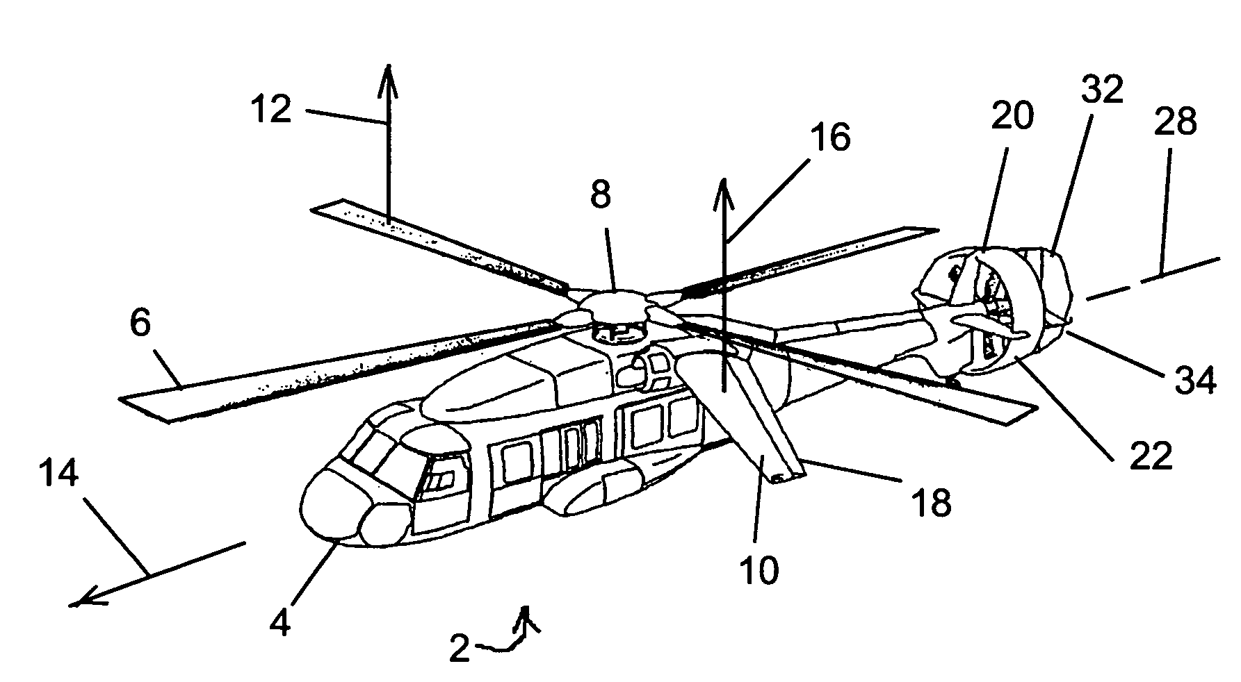
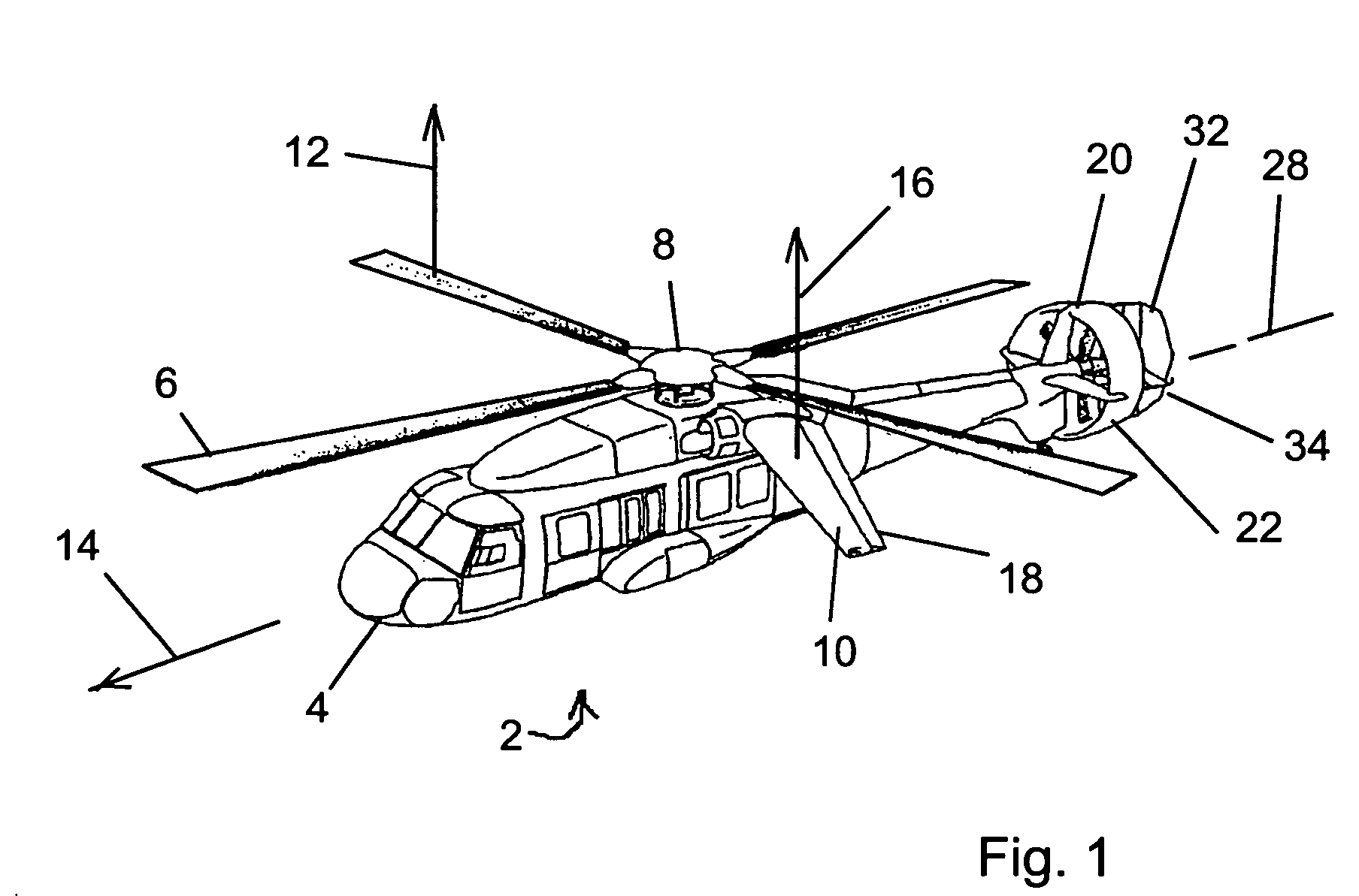
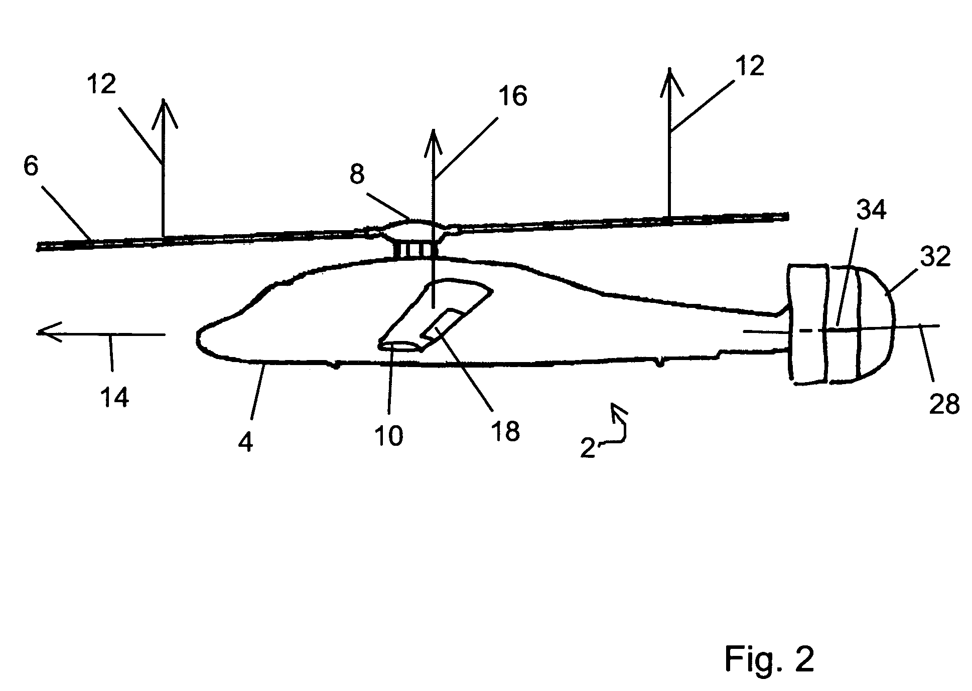
[0037]The apparatus of the Invention is a control system for a compound aircraft 2. As shown by FIGS. 1 and 2, the compound aircraft 2 includes features of both a helicopter and a fixed wing aircraft. Those features include a fuselage 4, a main rotor (or rotating wing) 6, a hub 8 about which the main rotor 6 rotates and wings 10. Rotation of main rotor 6 about hub 8 induces main rotor lift 12. Movement of air across wings 10 in response to the forward motion 14 of the compound aircraft 2 generates wing lift 16. Rotor lift 12 and wing lift 16 provide lift to the compound aircraft 2.

[0038]Wings 10 feature a wing control surface known as a ‘flaperon’18. Flaperon 18 may be moved differentially, in which event flaperons 18 act as ailerons. When used as ailerons, the flaperons 18 in conjunction with wings 10 impart a rolling moment to fuselage 4. The flaperons 18 also may be moved in unison, in which event the flaperons 18 act as flaps. When used as flaps, fla...


PUM


Abstract

The Invention is a control system for a compound aircraft. A compound aircraft has features of both a helicopter and a fixed wing aircraft and provides redundant control options. The control system allows an authorized person to select any of plurality of control biases each which is designed to achieve an overall operational objective. The control system applies the selected control bias in allocating the control function among the redundant control options.

Description

BACKGROUND OF THE INVENTION[0001]1. Field of the Invention[0002]The Invention is a control system for a compound aircraft. For trimmed flight, the control system selects a combination of trim control settings for the redundant controls of the compound aircraft to achieve a pilot's command consistent with a user-selectable objective, such as speed maximization, fuel consumption minimization, vibration reduction or lifecycle cost reduction. For maneuvering flight, the control system distributes control among the redundant control options of the compound aircraft and may perform that distribution consistent with the user-selectable objective. The Invention is also a method for controlling a compound aircraft.[0003]2. Description of the Related Art[0004]A ‘compound’ aircraft is an aircraft that includes features of both fixed wing aircraft and rotary wing aircraft. The compound aircraft includes the elements of a helicopter, including at least one main rotor and a mechanism to overcome ...

Claims


Application Information

Patent Timeline
Patent Type & Authority Patents(United States)
IPC IPC(8): B64C27/22G05D1/00
CPCB64C27/26B64C27/82B64C2027/8236B64C2027/829G05D1/0858
Inventor PIASECKI, FRANK N.GREENJACK, ANDREW S.HORN, JOSEPH F.
Owner PIASECKI AIRCRAFT CORP
Why Eureka
Try Eureka