Vehicle front structure

a front structure and vehicle technology, applied in the direction of roofs, bumpers, pedestrian/occupant safety arrangements, etc., can solve the problems of insufficient impact energy-absorbing capacity and difficulty in ensuring sufficient impact energy-absorbing capacity, so as to enhance impact energy-absorbing capacity, enhance repairability, and protect pedestrians. the effect of performan

Inactive Publication Date: 2008-10-21
MAZDA MOTOR CORP
View PDF2 Cites 30 Cited by
  • Summary
  • Abstract
  • Description
  • Claims
  • Application Information

AI Technical Summary

Benefits of technology

[0007]In view of the above technical problems and needs, it is an object of the present invention to provide a vehicle front structure capable of ensuring sufficient pedestrian protection performance by means of enhancing impact energy-absorbing capacity, while achieving enhanced repairability in the event of a low-impact collision.
[0009]In the vehicle front structure as mentioned above, the second shock-absorbing module makes it possible to provide enhanced impact energy-absorbing capacity to the vehicle front structure so as to ensure sufficient pedestrian protection performance while achieving enhanced repairability in the event of a low-impact collision.

Problems solved by technology

In the structure disclosed in Patent Publication 1, although the intended purpose of pedestrian protection can be effectively achieved by means of flicking legs of a pedestrian during a frontal impact with the pedestrian, it is difficult to ensure sufficient impact energy-absorbing capacity.
In the structure disclosed in Patent Publication 2, although a certain level of impact energy-absorbing capacity can be ensured, it is still not enough to meet rising demand.

Method used


Image

  • Vehicle front structure
  • Vehicle front structure
  • Vehicle front structure

Examples


Embodiment Construction

[0020]With reference to the accompanying drawings, an embodiment of the present invention will now be described.

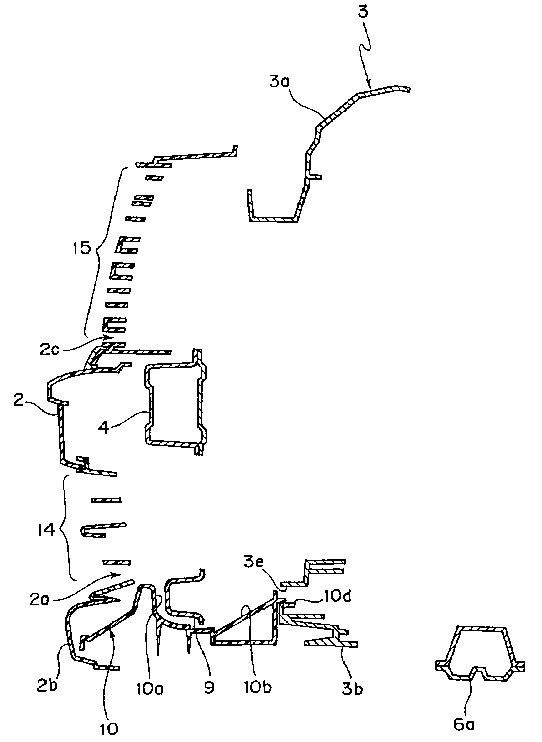
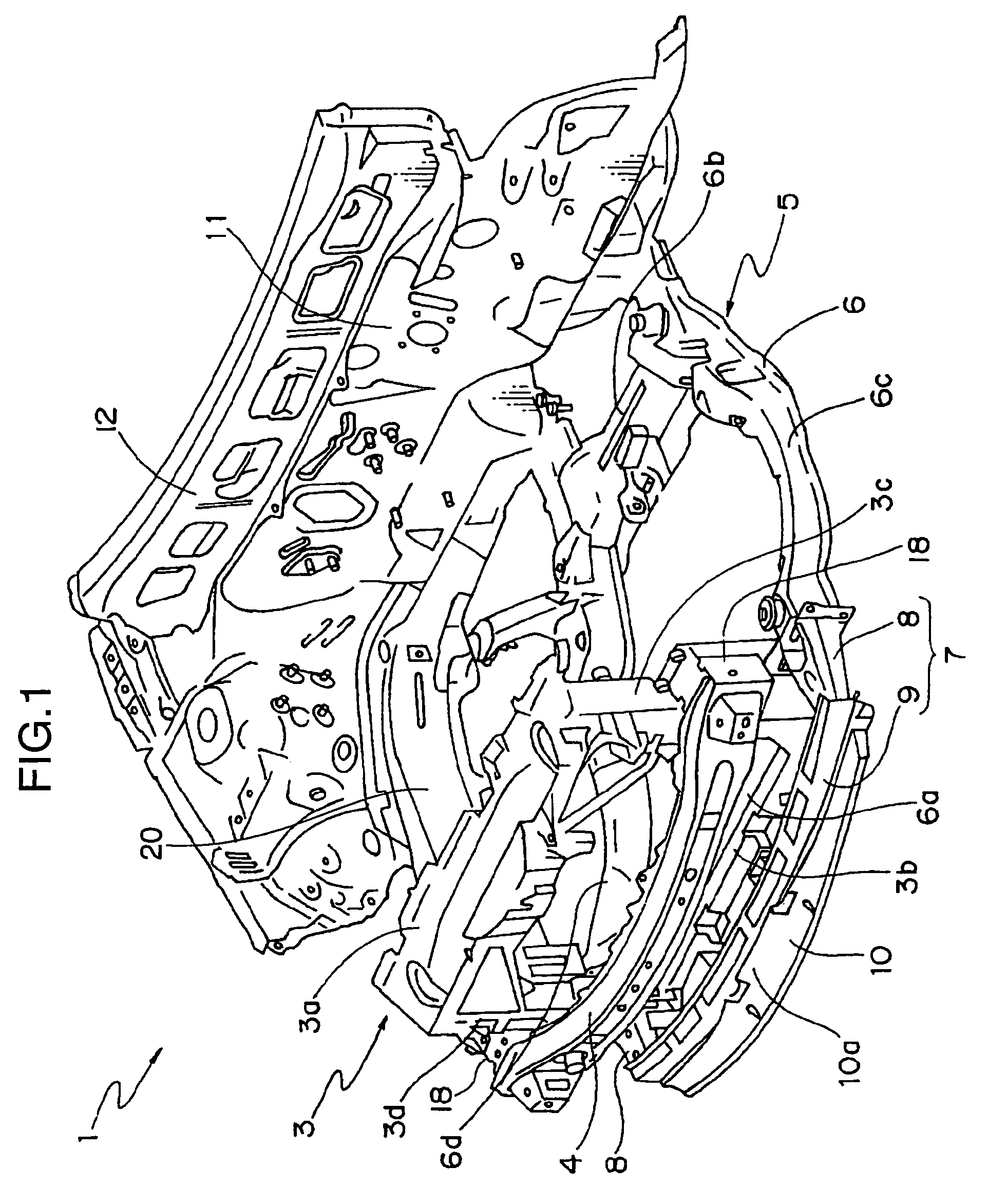
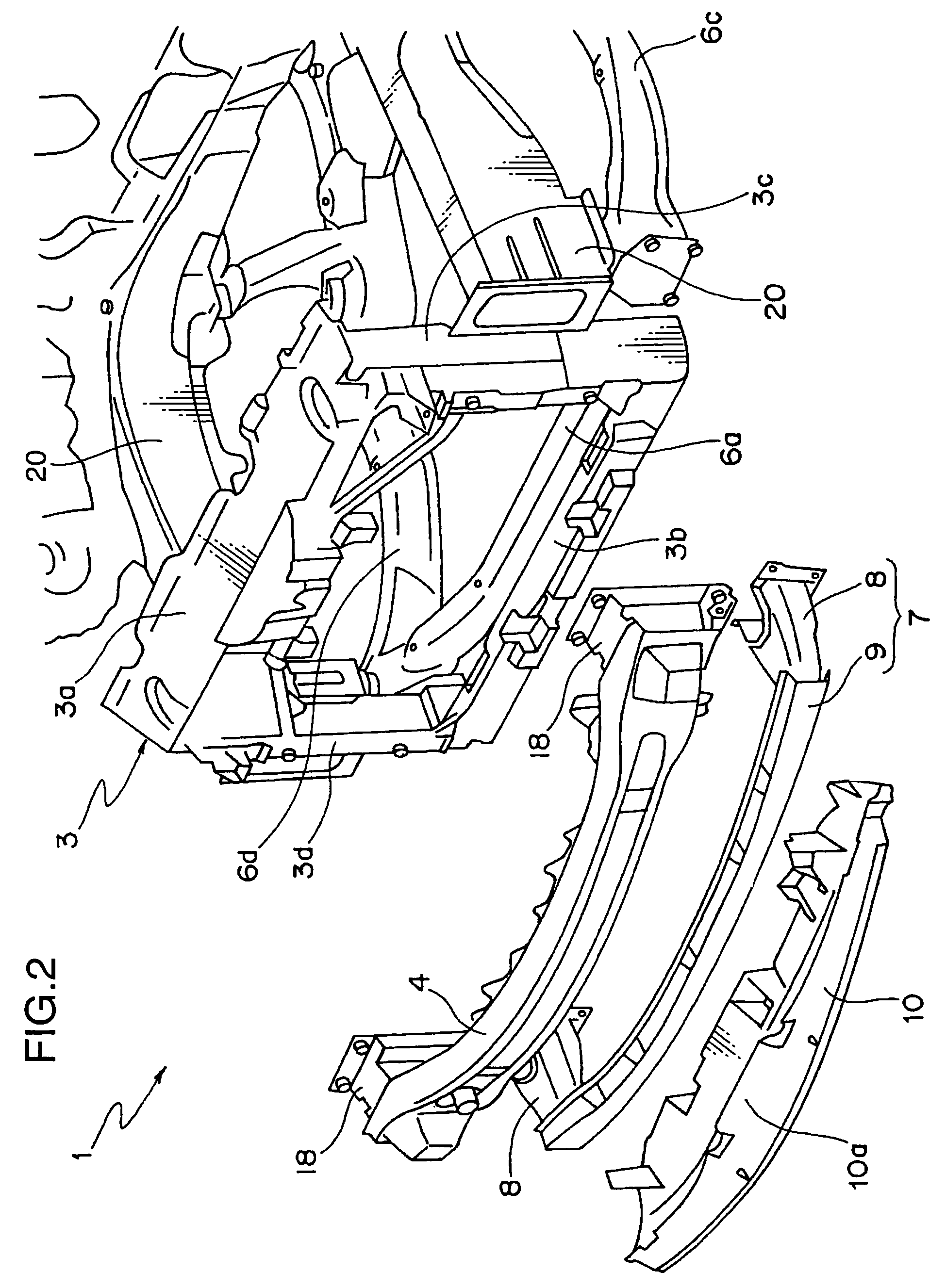
[0021]FIG. 1 is a perspective view showing a vehicle front structure according to one embodiment of the present invention, wherein a reinforcing structure and a shock-absorbing structure on an inward side relative to a bumper fascia are generally illustrated. FIG. 2 is an exploded perspective view showing the vehicle front structure, and FIG. 3 is a fragmentary perspective view showing the vehicle front structure, wherein an approximately half of the vehicle front structure is cut out along a vertical plane extending in a longitudinal direction of the vehicle across a laterally central region of the vehicle. While the vehicle front structure of the present invention essentially comprises a bumper fascia, a vehicle-body component associated therewith, and a vehicle-body component on a left side of the vehicle (lower right side in FIG. 1), such as a left front side frame, th...


PUM


Abstract

Disclosed is a vehicle front structure, which comprises a bumper fascia 2, a lower shroud member 3b, a subframe 5 including a first shock-absorbing module 7, and a second shock-absorbing module 10 having a stiffness less than that of the first shock-absorbing module 7. A subframe body 6 is formed in an approximately rectangular shape and disposed on a rear side of the lower shroud member 3b. The first shock-absorbing module 7 includes an energy-absorbing section 8, 8 and a beam member 9. The energy-absorbing section 8, 8 has a configuration which extends frontwardly from respective front end regions of the subframe body 6 located on laterally-opposite sides thereof, along respective opposite lateral surfaces of the lower shroud member 3b, and the beam member 9 has a configuration bridging between respective front ends of the energy-absorbing section 8, 8, at a height position approximately equal to or adjacent to that of a lower edge of the lower shroud member 3b. The second shock-absorbing module 10 has a bulging portion 10a which covers at least a part of a front surface of the beam member 9. The vehicle front structure of the present invention can ensure sufficient pedestrian protection performance by means of enhancing impact energy-absorbing capacity, while achieving enhanced repairability in the event of a low-impact collision.

Description

BACKGROUND OF THE INVENTION[0001]1. Field of the Invention[0002]The present invention relates to a vehicle front structure.[0003]2. Background Art[0004]Heretofore, there have been known various vehicle front structures intended for the protection of pedestrians. As an example, JP 2006-001358A (‘Patent Publication 1’) discloses a vehicle front structure comprising a plate member which extends from a lower shroud member to a position adjacent to a bottom surface of a bumper fascia so as to flick legs of a pedestrian during a frontal impact with the pedestrian. In this type of vehicle front structure, there has also been proposed an improved structure intended to provide enhanced absorbing capacity of impact energy during a frontal collision. For example, JP 2005-271810A (‘Patent Publication 2’) discloses a vehicle front structure comprising a beam member which bridges between right and left crush cans fixed to a front end of a subframe.[0005]In the structure disclosed in Patent Public...

Claims


Application Information

Patent Timeline
Patent Type & Authority Patents(United States)
IPC IPC(8): B60K11/04B60J7/00
CPCB62D21/152B62D25/084B60R19/12B60R21/34B60R2021/0004B60R2021/0053
Inventor NAKAMAE, TAKAYUKIKAGEYAMA, YASUNORINAKAYAMA, NOBUYUKISUNAKAWA, TAKAYUKI
Owner MAZDA MOTOR CORP
Why Eureka
Try Eureka