Fan

a fan and fan body technology, applied in the field of fans, can solve the problems of limited sickling degree, axial length of such a fan might become too large, and achieve the effects of reducing noise level, minimizing air leakage, and reducing noise level

Active Publication Date: 2008-10-21
EBM PAPST ST GEORGEN & -
View PDF24 Cites 19 Cited by
  • Summary
  • Abstract
  • Description
  • Claims
  • Application Information

AI Technical Summary

Benefits of technology

[0005]According to a first aspect of the invention, this object is achieved by a fan in which the fan blades are sickle-shaped and are provided, adjacent their tips, with flow-pattern obstacles which minimize air leakage between the intake side of the fan and the delivery side of the fan. It has been shown that, surprisingly, in such a fan the fan noise decreases, in particular, in the so-called laminar region, i.e. with high conveying volumes and a relatively small pressure rise Δp. A noise reduction occurs with such a fan in the non-laminar region as well, i.e. with higher back pressures and smaller air quantities. A theoretical explanation might be that an air flow occurs along the sickle-shaped front edges of the fan blades, and this air flow flows practically as far as the outer periphery of the hub, where the circumferential velocity is lowest, and consequently little noise is generated by this flow. The degree of sickling is, of course, limited by the fact that with a very pronounced sickle shape, the axial length of such a fan might become too great.
[0006]The stated object is achieved in another way by providing ends of the fan blades with flow elements which themselves are airfoil-shaped and which, in a middle region between their front and back edges, are wider than an adjacent part of the fan blade. It has been shown that this type of configuration of the profile of the blade and flow element contributes to particularly quiet running of the fan.

Problems solved by technology

The degree of sickling is, of course, limited by the fact that with a very pronounced sickle shape, the axial length of such a fan might become too great.

Method used


Image

  • Fan
  • Fan
  • Fan

Examples


Embodiment Construction

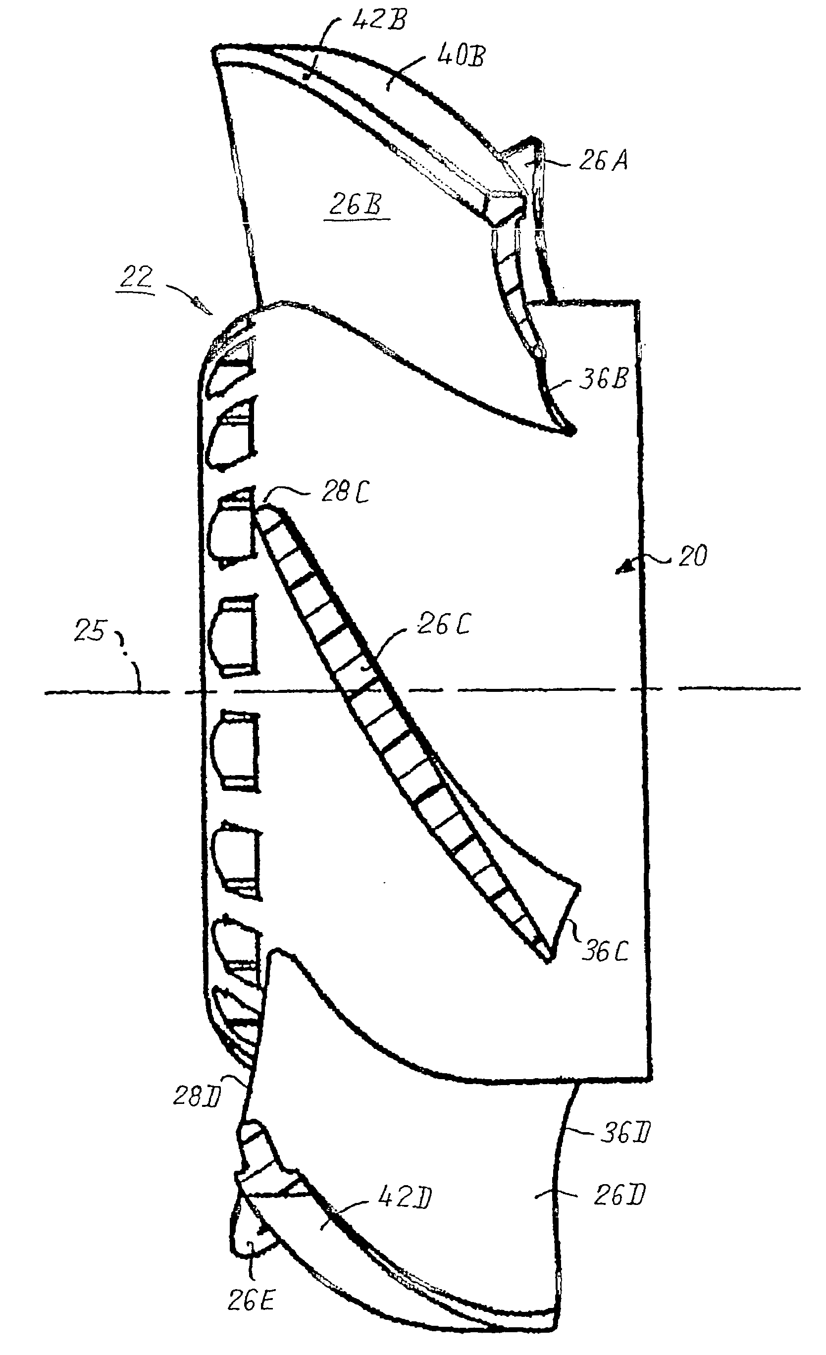
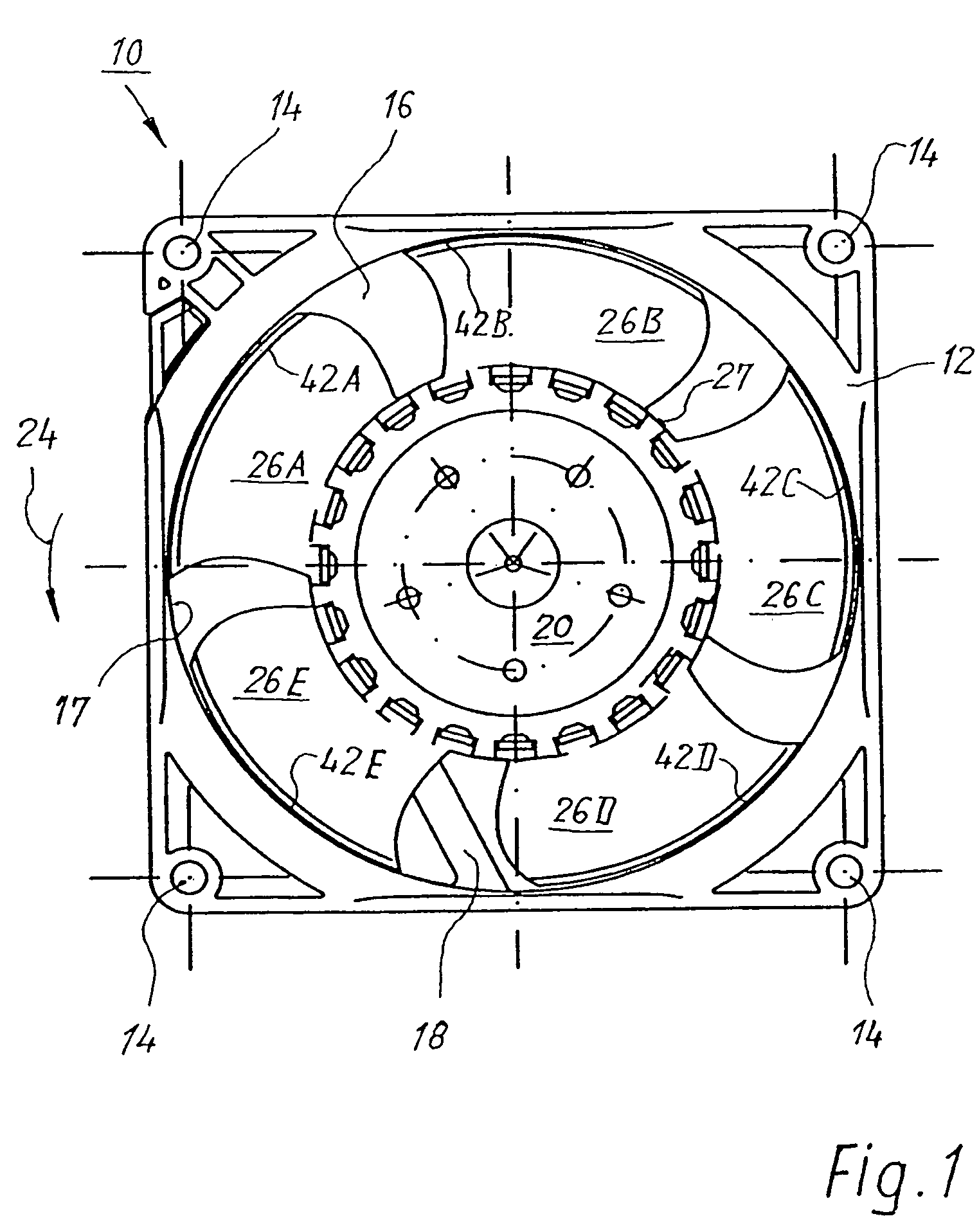
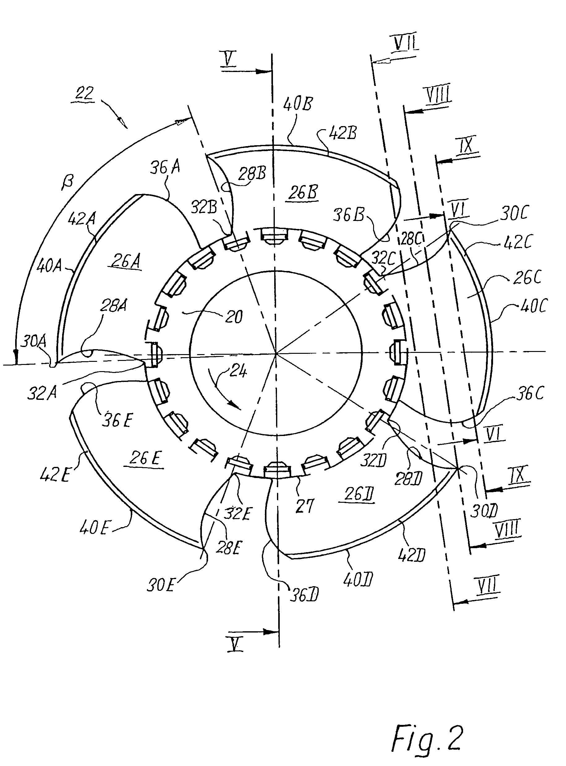
[0023]In the figures that follow, the same reference characters are used in each case for identical or identically functioning components, incremented by 100 if applicable (e.g. 122 instead of 22), and these components are usually described only once.

[0024]FIG. 1 shows an equipment fan 10 of ordinary design. The present invention can be realized implemented in an axial fan and, alternatively, in a diagonal fan. Fan 10, depicted in FIG. 1, has an external housing 12, at the four corners of which respective mounting openings 14 are provided and which defines in its interior an air conveying conduit 16, which conduit is limited toward the outside by a rotation surface 17 and in which conduit is rotatably mounted, via struts 18, the central hub 20 of a fan wheel 22 that, in operation, is rotated about a central axis 25 (FIGS. 4 and 5) by an electric motor arranged inside this hub 20. In FIG. 1, hub 20 rotates counterclockwise in the direction of an arrow 24. The air flow is such that th...


PUM


Abstract

A fan has an air conveying conduit (16) and a fan wheel (22) arranged therein, which wheel is rotatable about a central axis (25) and is formed with a central hub (20; 120) having an outer periphery (27) on which fan blades (26) are mounted. These extend with their radially outer rims (40) as far as a surface (17) that is substantially coaxial with the central axis (25) and delimits the air conveying conduit (16) externally. The blades (26) have a profile similar to an airfoil profile. A flow element (42) is provided along the radial outer edge (40) of a fan blade and serves as an obstacle to a compensating flow proceeding around that radial outer edge (40) from the delivery side to the intake side, and likewise has, in cross section, an airfoil profile.Adjacent the front edge (28) and rear edge (36) of a blade (26), it has substantially the same outline as the adjacent part of the associated blade (26), and in a middle region (48) between the front and back edge is wider, by an approximately constant amount, than the adjacent part of the blade (26).

Description

CROSS REFERENCE[0001]This application is a section 371 of PCT / EP 2004 / 003916, filed 14 Apr. 2004, published 4 Nov. 2004 as WO 2004 / 094835-A1.FIELD OF THE INVENTION[0002]The present invention relates to a fan having an air conveying conduit and having a fan wheel arranged rotatably therein, the blades of which wheel are equipped, in the region of their external edges, with flow elements that have low resistance to the conveyed flow and that constitute an obstacle to the compensating flows proceeding around the outer edges of the blades from the delivery side to the intake side.BACKGROUND[0003]A fan having such flow elements is known from the commonly assigned DE 30 17 226 A and corresponding GB 2 050 530-A, HARMSEN. This These unexamined applications describes a variety of designs for such flow elements, in combination with fan blades stamped out of sheet metal. These flow elements reduce the leakage flow in a fan equipped therewith.SUMMARY OF THE INVENTION[0004]It is an object of th...

Claims


Application Information

Patent Timeline
Patent Type & Authority Patents(United States)
IPC IPC(8): F04D29/38F04D29/16
CPCF04D29/164F04D29/384F05D2240/307
Inventor EIMER, GEORG
Owner EBM PAPST ST GEORGEN & -
Why Eureka
Try Eureka