Terminal Block for Connecting Electric Cables

a technology of connecting electric wires and terminal blocks, which is applied in the direction of multiple conductor connectors, contact member manufacturing, electrical apparatus, etc., can solve the problems of high cost, inconvenient assembly, and inability to accurately measure the reading of instruments, and achieves the effect of easy and inexpensive production and assembly

Active Publication Date: 2008-10-21
MORSETTITALA
View PDF5 Cites 18 Cited by
  • Summary
  • Abstract
  • Description
  • Claims
  • Application Information

AI Technical Summary

Benefits of technology

[0012]In connection with this problem it is also required that this terminal block should consist of a small number of component parts and should be easy and inexpensive to produce and assemble and have minimum dimensions.

Problems solved by technology

Although fulfilling their function, these known terminal blocks nevertheless have drawbacks in particular with regard to certain applications such as connection of the output wires from a thermocouple which, as is known, are made of a different material and must be connected without creating a difference in potential which would give rise to an incorrect measurement read off the instrument situated remotely.
In the first case this results in terminal blocks which are extremely precise, but which also have a high cost owing to the double terminals and the presence of the bars made of different material; in the second case the design is simplified, but at the cost of much less precision owing to the direct clamping action by means of screws.
The technical problem which is posed, therefore, is that of providing a terminal block for electrically connecting discontinuous wires, in particular for measuring instruments such as thermocouples and the like, which is able to ensure a very precise electrical connection without creating differences in potential and is essentially independent of the material and the cross-section of the wires to be connected.

Method used


Image

  • Terminal Block for Connecting Electric Cables
  • Terminal Block for Connecting Electric Cables

Examples


Embodiment Construction

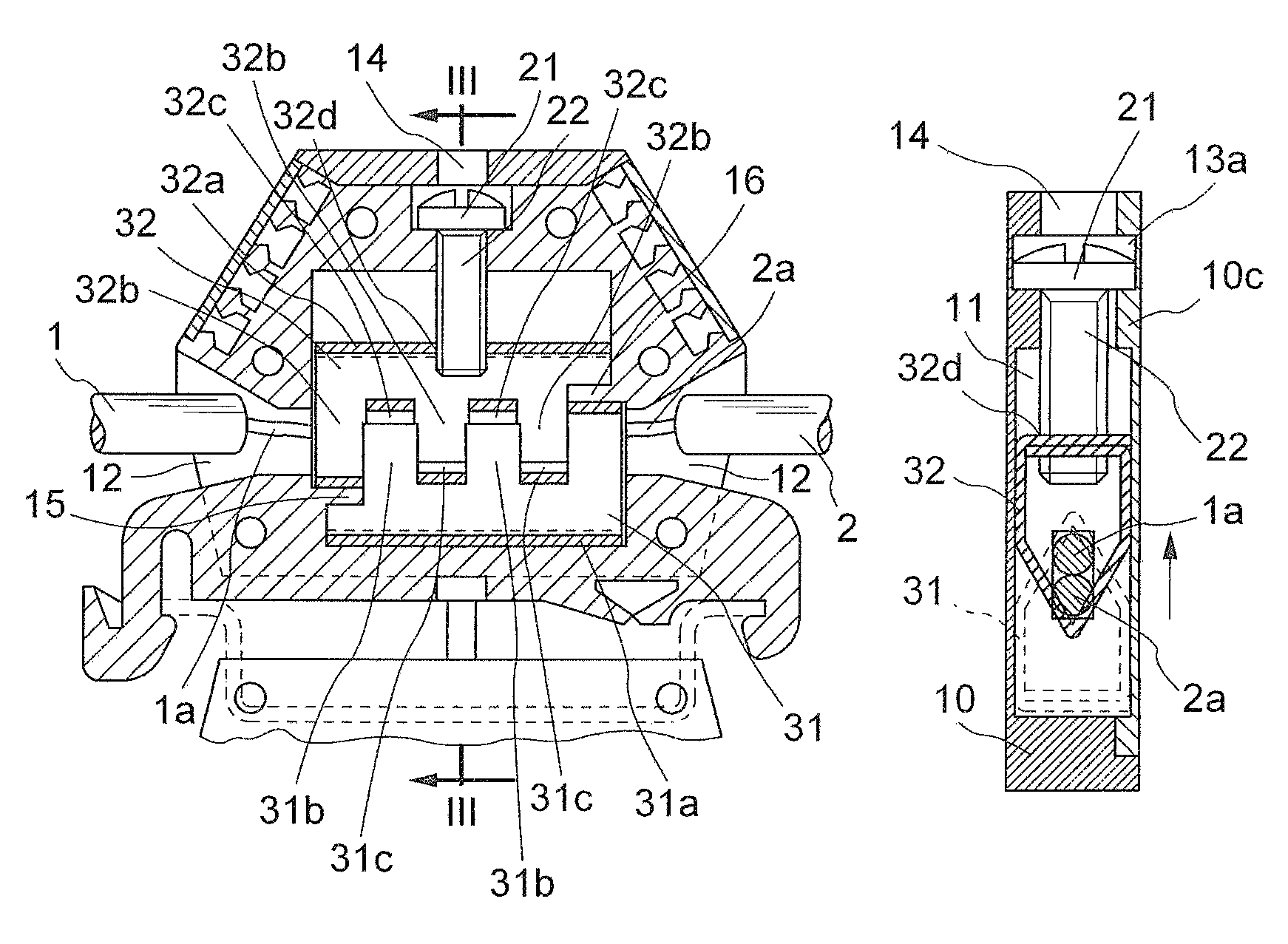
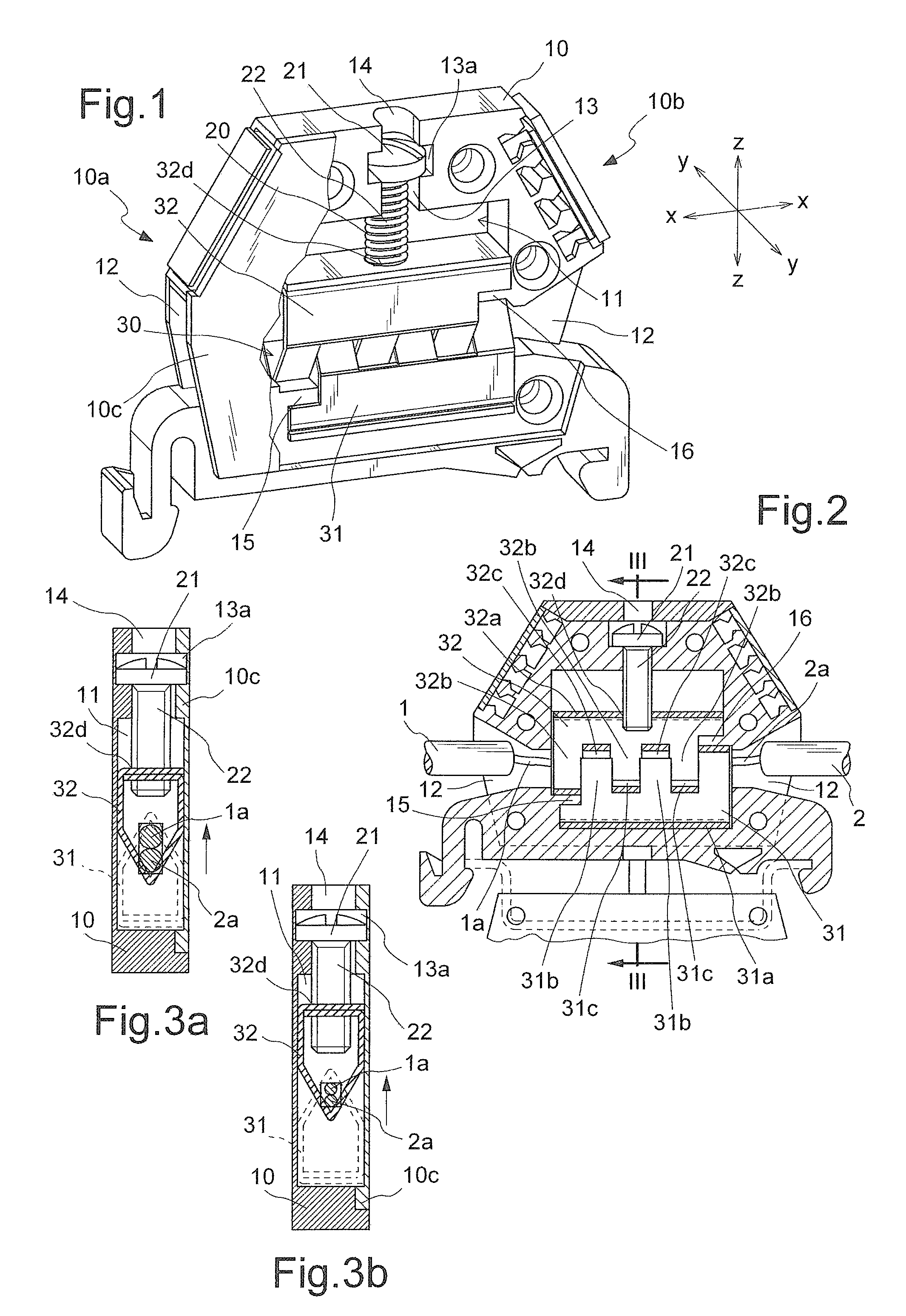
[0019]As shown in FIG. 1 and assuming solely for the sake of convenience of the description and without limiting the scope of the invention, a set of three reference axes with a longitudinal direction X-X, transverse direction Y-Y and vertical direction Z-Z, respectively, as well as an upper part corresponding to the part for access to the clamping screw and a bottom part opposite to the first part, the terminal block according to the present invention comprises essentially a body 10 made of insulating material and having formed therein:[0020]a central chamber 11 for housing means 20 for clamping the ends 1a,2a of the electric wires 1,2 to be connected together electrically;[0021]two opposite seats 12 which are respectively open outwards on the sides 10a, 10b of the body 10 of the terminal block for inserting the said wires 1,2 in the longitudinal direction X-X;[0022]a front closing cover 10c.

[0023]In greater detail, said chamber 11 is connected to an upper opening 14 by means of a...


PUM


Abstract

Terminal block comprising a body having, formed internally, a chamber for housing a clamp for retaining the ends of electric cables or wire, which can be operated by an operating mechanism, at least two openings for introducing said wires, at least one opening for access to the operating mechanism, the clamp consisting of at least two jaws which are situated opposite each other in the direction (Z-Z) transverse to the longitudinal direction of the electric wires and respectively comprising at least one base and at least one pair of lugs which are discontinuous in the longitudinal direction (X-X) so as to define respective seats suitable for engagement in the vertical direction (Z-Z) with corresponding lugs of the other jaw and each of the lugs having a cross-section substantially in the form of an isosceles triangle.

Description

BACKGROUND[0001]1. Technical Field of the Invention[0002]The present invention relates to a terminal block for connecting electric wires.[0003]2. Description of the Prior Art[0004]It is known in the technical sector relating to the manufacture of switchboards for the wiring of electrical installations to use terminal blocks which are able to be mounted on associated supports and have opposite side openings for introducing in the longitudinal direction discontinuous wires to be connected electrically together by tightening a part movable in the direction transverse to the longitudinal direction of the wires.[0005]Although fulfilling their function, these known terminal blocks nevertheless have drawbacks in particular with regard to certain applications such as connection of the output wires from a thermocouple which, as is known, are made of a different material and must be connected without creating a difference in potential which would give rise to an incorrect measurement read off...

Claims


Application Information

Patent Timeline
Patent Type & Authority Patents(United States)
IPC IPC(8): H01R11/09
CPCH01R4/42H01R9/26H01R9/24H01R43/16
Inventor PIZZI, GIORDANO
Owner MORSETTITALA
Why Eureka
Try Eureka