High-current electrical coil, and transformer construction including same

a transformer and high-current technology, applied in the direction of transformers/inductance details, coils, electrical equipment, etc., can solve the problems of relatively high construction cost and volume production, and achieve the effects of low cost, compact and efficient transformer construction, and high curren

Inactive Publication Date: 2008-10-21
TDK LAMBDA CORP
View PDF7 Cites 47 Cited by
  • Summary
  • Abstract
  • Description
  • Claims
  • Application Information

AI Technical Summary

Benefits of technology

[0004]An object of the present invention is to provide an electrical coil particularly useful for high-current transformers which can be produced in volume at relatively low cost. Another object of the invention is to provide a high current electrical coil particularly useful in constructing small, compact and efficient transformers. A further object of the present invention is to provide a transformer which can be operated efficiently, and can be produced in a small and compact form in volume and at relatively low cost.
[0008]According to a still further feature in the described preferred embodiments, the inner edge of one of the electrically-conductive elements is recessed at an intermediate portion thereof with respect to the aligned intermediate portions of the other electrically-conductive element and of the electrically insulative element to increase the creepage distance for the conduction of electricity over the electrically insulative element from one electrically-conductive element to the other electrically-conductive element. Also, the inner edge of the other of said electrically-conductive elements is similarly recessed at an intermediate portion thereof opposite to that of the recessed portion of the one electrically-conductive element.
[0012]As will be described more particularly below, the foregoing features enable the construction of compact and efficient electrical coils and transformers having a few relatively simple parts which can be produced and assembled in volume and at relatively low cost.

Problems solved by technology

Such a construction, however, is relatively expensive to produce in volume.

Method used


Image

  • High-current electrical coil, and transformer construction including same
  • High-current electrical coil, and transformer construction including same
  • High-current electrical coil, and transformer construction including same

Examples


Embodiment Construction

Overall Transformer Construction

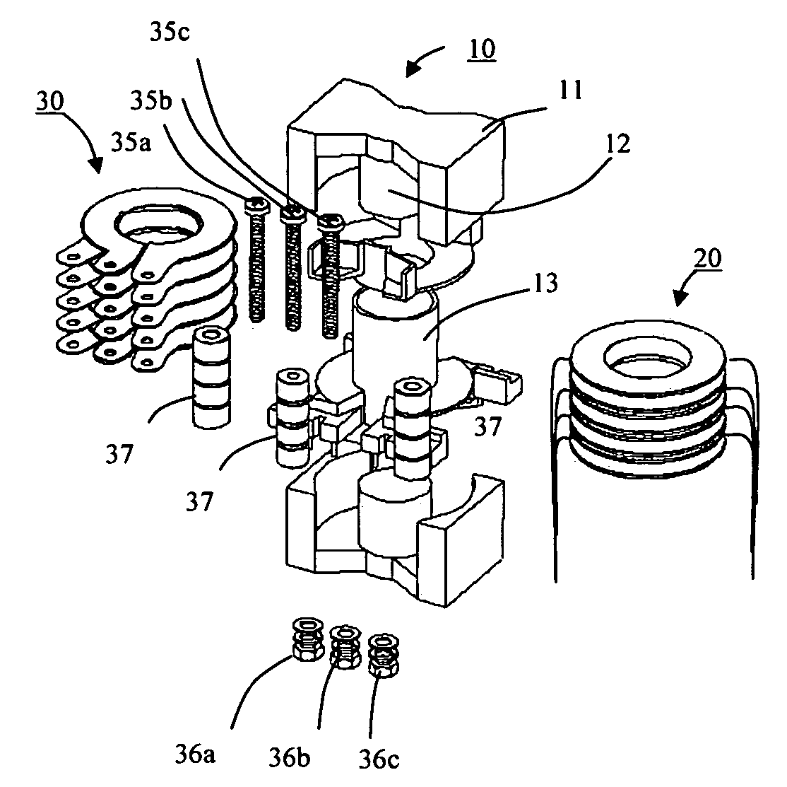
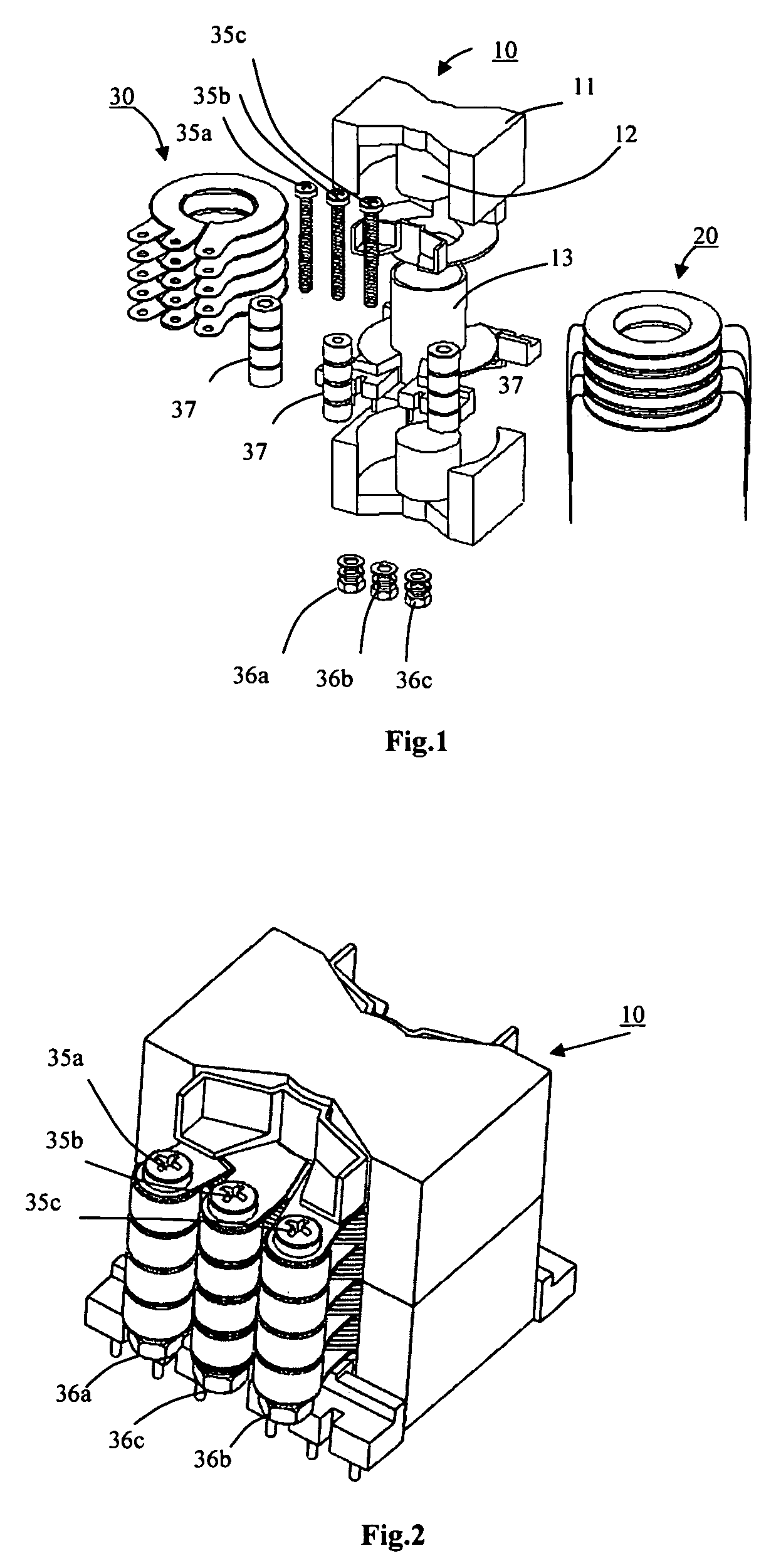
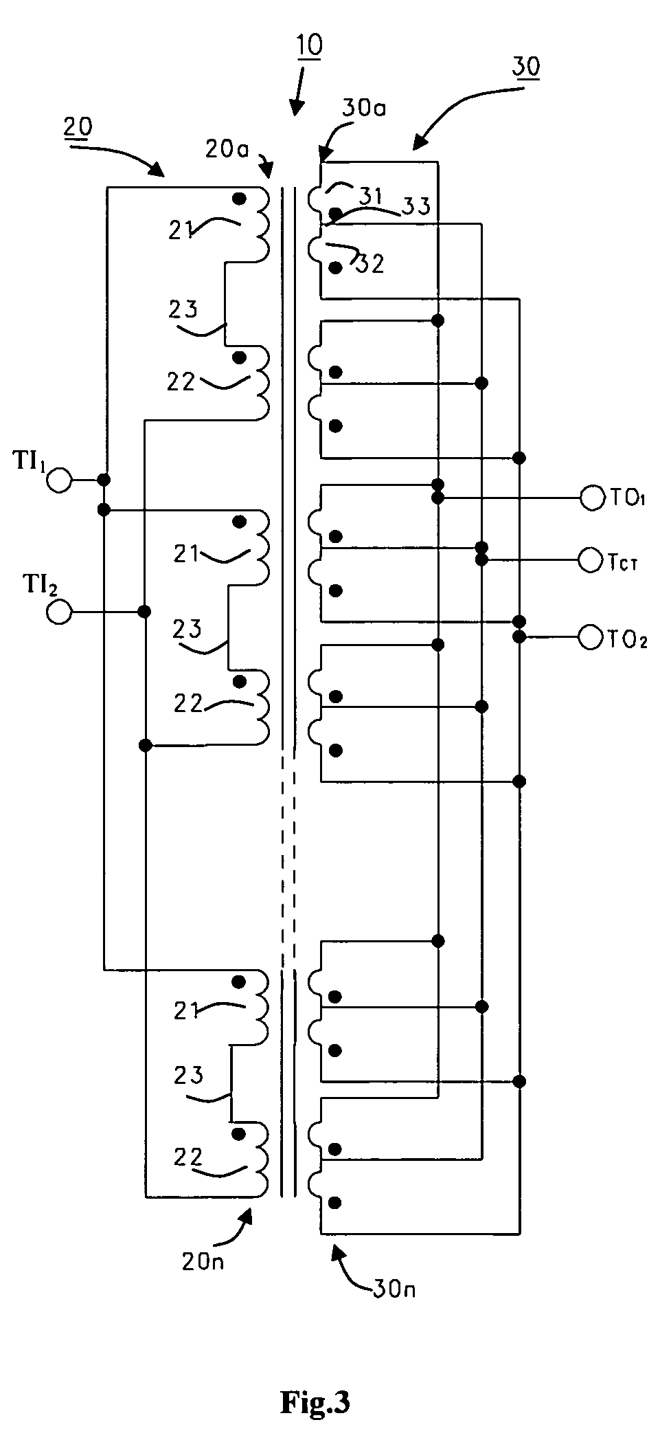
[0032]A transformer constructed in accordance with the present invention is illustrated in FIGS. 1 and 2. The illustrated transformer includes a magnetic core assembly, generally designated 10; a primary winding assembly, generally designated 20; and a secondary winding assembly, generally designated 30, electromagnetically coupled to the primary winding assembly 20.

[0033]As shown particularly in FIG. 1, the magnetic core assembly 10 includes an outer magnetic section 11, and an inner core section 12 of cylindrical configuration extending longitudinally of the transformer. As known, the inner core section 12 may be interrupted to produce an air gap to prevent saturation. The inner core section 12 is enclosed by a cylindrical bobbin 13 of electrically insulating material for supporting the two winding assemblies 20 and 30. FIG. 1 illustrates the coils of the two assemblies as being interleaved, as shown in the above-cited U.S. Pat. No. 5,331,536.

[0034]...


PUM

PropertyMeasurementUnit
electrically-conductiveaaaaaaaaaa
electrical insulationaaaaaaaaaa
DC voltagesaaaaaaaaaa

Abstract

An electrical coil includes first and second electrically-conductive elements each of a thin, flat, annular configuration formed with a gap to define the turns of a 2-turn coil, and an electrically insulative element also of a thin, flat, annular configuration disposed coaxially between the two electrically-conductive elements and formed with a gap aligned with one end of each turn to permit the ends to be electrically connected together. Also described is a transformer having a secondary winding including a plurality of such 2-turn coils, and a primary winding of a plurality of double-coils each connected together at their mid-portions.

Description

FIELD AND BACKGROUND OF THE INVENTION[0001]The present invention relates to electrical coils, and to transformer constructions including such electrical coils. The invention is particularly useful with respect to high-current, low-leakage transformers, and is therefore described below with respect to such a transformer construction.[0002]High-current, low-leakage transformers are commonly used in power supplies for supplying low DC voltages, e.g. in computers. Such power supplies should be characterized by: small and compact construction, in order to occupy a minimum of volume; low creepage and efficient operation at high frequencies, in order to reduce heat losses and prevent excessive temperature rises; and low leakage inductance to enable high frequency operation. In addition, they should be constructed of a relatively few simple parts which can be produced and assembled in volume and at relatively low cost.[0003]Many such power supplies have been developed and are described in t...

Claims


Application Information

Patent Timeline
Patent Type & Authority Patents(United States)
IPC IPC(8): H01F5/00
CPCH01F5/003H01F27/2804H01F27/29H01F27/323H01F27/325H01F2027/2809
Inventor PODLISK, ILIARUCAREANU, GEORGE
Owner TDK LAMBDA CORP
Why Eureka
Try Eureka