Closure device for a withdrawable rack

Inactive Publication Date: 2008-10-21
SIEMENS AG
View PDF9 Cites 46 Cited by
  • Summary
  • Abstract
  • Description
  • Claims
  • Application Information

AI Technical Summary

Benefits of technology

[0011]According to another feature of the present invention, a locking mechanism may be provided for locking the closed position of the plate arrangement, with the locking mechanism being constructed to simultaneously engage the actuating element and a structural component of the closure device separate from the actuating element. In this way, an operator is prevented from inadvertently pushing the actuating element by hand so as to open the closure device and unintentionally expose the contact blades and thus run the risk of an electric shock. The actuating element may have a plate-shaped configuration, with the locking mechanism including two locking plates disposed on the actuating element in side-by-side relationship or placed on top of each other. Suitably, the locking plates can be con

Problems solved by technology

This prevents the actuating element from being subjected to additional forces from the power circuit breaker after the

Method used


Image

  • Closure device for a withdrawable rack
  • Closure device for a withdrawable rack
  • Closure device for a withdrawable rack

Examples


Embodiment Construction

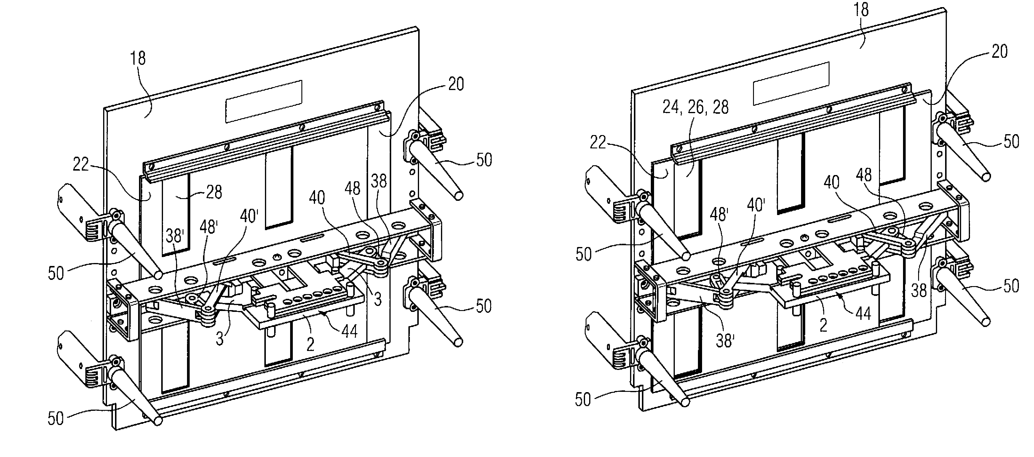
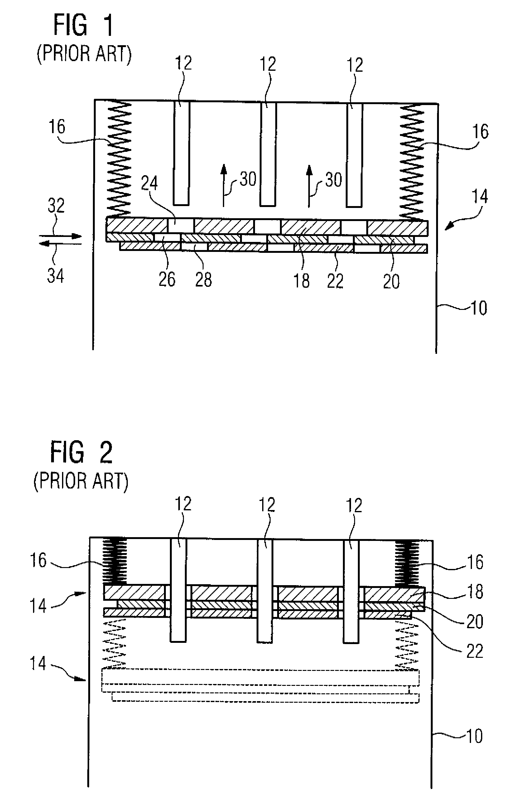
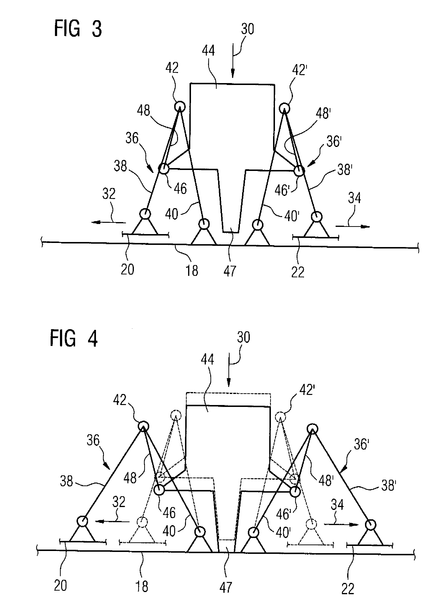
[0024]Throughout all the Figures, same or corresponding elements are generally indicated by same reference numerals. These depicted embodiments are to be understood as illustrative of the invention and not as limiting in any way. It should also be understood that the figures are not necessarily to scale and that the embodiments are sometimes illustrated by graphic symbols, phantom lines, diagrammatic representations and fragmentary views. In certain instances, details which are not necessary for an understanding of the present invention or which render other details difficult to perceive may have been omitted.

[0025]Turning now to the drawing, and in particular to FIG. 1, there is shown schematically a withdrawable rack 10 intended for insertion of a power circuit breaker. The power circuit breaker is configured to receive electric energy via contact blades 12 which carry a high voltage. Therefore, the contact blades 12 should not be accessible from the open end of the withdrawable r...


PUM


Abstract

A closure device for a withdrawable rack adapted for receiving power circuit breaker includes a plate arrangement having at least two plates provided with openings and movable relative to one another so that the plate arrangement is changeable between an open position in which the openings of the plates are in alignment and a closed position in which the openings are out of alignment. An actuating mechanism is acted upon by the power circuit breaker as it is inserted to cause a movement of at least one of the plates to thereby change the plate arrangement between the closed and open positions. The actuating mechanism includes two V-shaped linkage assemblies. Each linkage assembly has two legs connected by a hinge to allow the linkage assembly to spread apart, with one of the legs having a free end which is connected to the at least one of the plates, and a coupler is connected to the hinge. Both couplers are jointly articulated to actuating element.

Description

BACKGROUND OF THE INVENTION[0001]The present invention relates to a closure device for a withdrawable rack or module frame in which an electric switch, such as a power circuit breaker, can be inserted.[0002]Nothing in the following discussion of the state of the art is to be construed as an admission of prior art.[0003]In the following description, reference is made in general to “power circuit breaker” which should be understood in a generic sense to cover any type of electric switch for insertion into a withdrawable rack.[0004]A closure device, which is also known as shutter, for a withdrawable rack is provided to prevent personnel in the vicinity of the withdrawable rack from accidentally touching exposed live contacts, such as contact blades located on the rear wall of the withdrawable rack, when the withdrawable rack is open, i.e., when a power circuit breaker is not inserted. Otherwise, personnel may receive a lethal electric shock when touching the exposed contacts. As protec...

Claims


Application Information

Patent Timeline
IPC IPC(8): H02B1/14H02B11/24
CPCH02B11/24
Inventor DEYLITZ, ERHARDENGEMANN, BURKHARDLOSCH, STEFAN
Owner SIEMENS AG
Why Eureka
Try Eureka