Water flow detection system for a bathing unit

a control system and bathing unit technology, applied in the direction of structural/machine measurement, application, lighting and heating apparatus, etc., can solve the problems of increasing the risk of damage to the bathing unit components and the piping system, the risk of overheating in new bathing units, and the thermal properties of plastic materials that are generally inferior to metallic materials

Active Publication Date: 2008-10-21
GECKO ALLIANCE GROUP
View PDF34 Cites 57 Cited by
  • Summary
  • Abstract
  • Description
  • Claims
  • Application Information

AI Technical Summary

Problems solved by technology

A consideration associated with the heating of the water is the risk of damage to the heating element, the bathing unit components and the piping system when the heating element becomes too hot.
The risk of damage due to overheating is increased in new bathing units since the current trend is to construct heating modules with plastic components.
However, plastic materials generally have thermal properties that are inferior to metallic materials.
Dry fires occur when there is no water in the heating module or when the flow of water is too weak to remove enough heat from the heating module.
The insufficiency of water flow through the heating module may create some hot spots on the heating element, which can damage and / or decrease the life expectancy of the heating element.
Insufficient flow or an insufficient level of water in the heating module can occur as a result, for example, of a blockage in the piping system, a dirty filter system preventing the normal flow of water in the heating module or simply from a low water level in the water holding receptacle.
However, this method does not give any indication as to the level of water flow through the heating module, and as mentioned above, the risk of damage due to overheating is increased if the flow inside the heating module is weak.
In addition, such pressure switches have a limited life span due to the fact that they include moving parts that can deteriorate and break.
They also need calibration due to the fact that they shift over time.
A deficiency with this system is that multiple components are required in order to determine the flow of water.
Based on the above, it would seem that existing systems offer no suitable manner for detecting if there is sufficient flow within the heating module.

Method used


Image

  • Water flow detection system for a bathing unit
  • Water flow detection system for a bathing unit
  • Water flow detection system for a bathing unit

Examples


Embodiment Construction

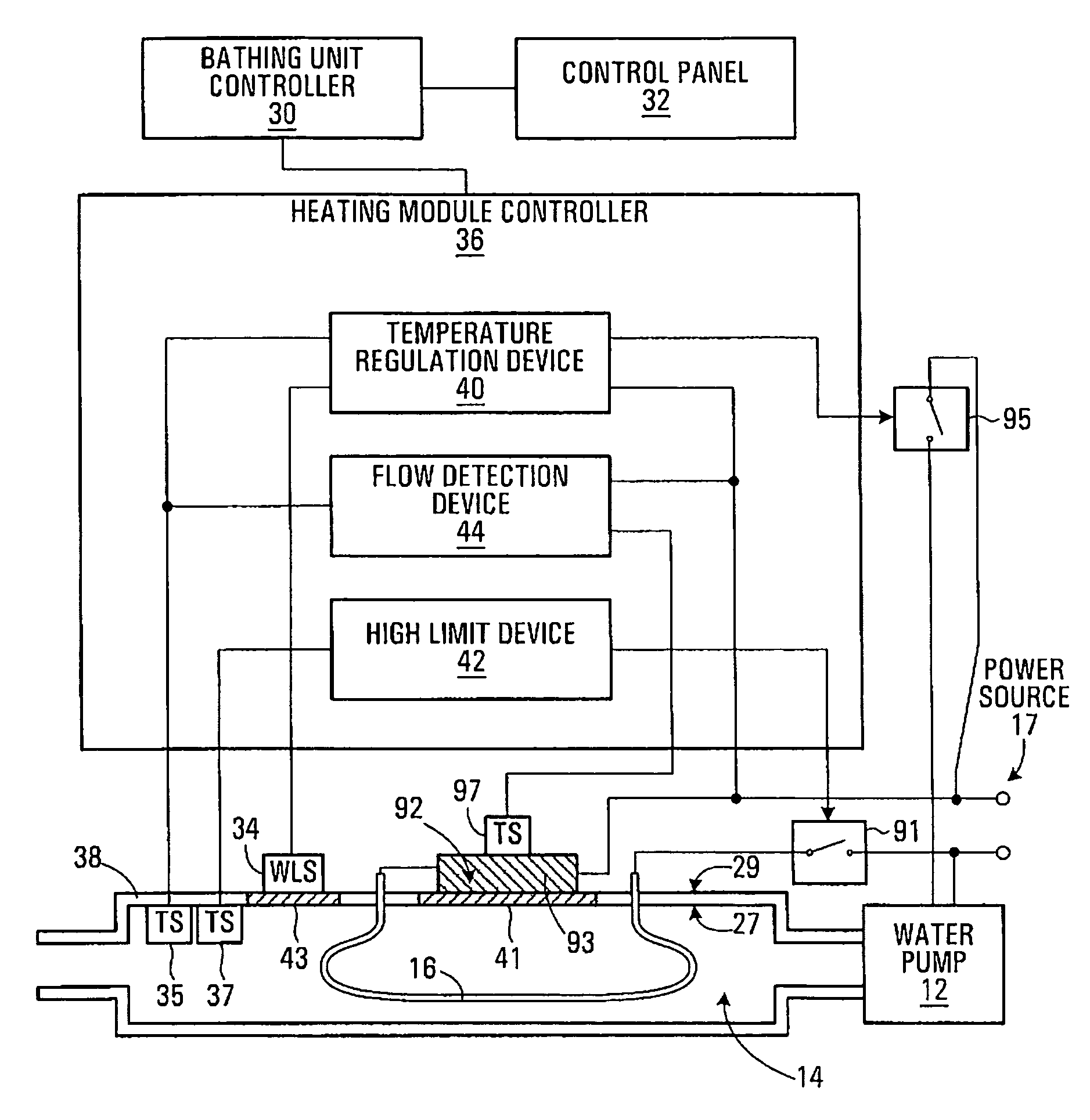
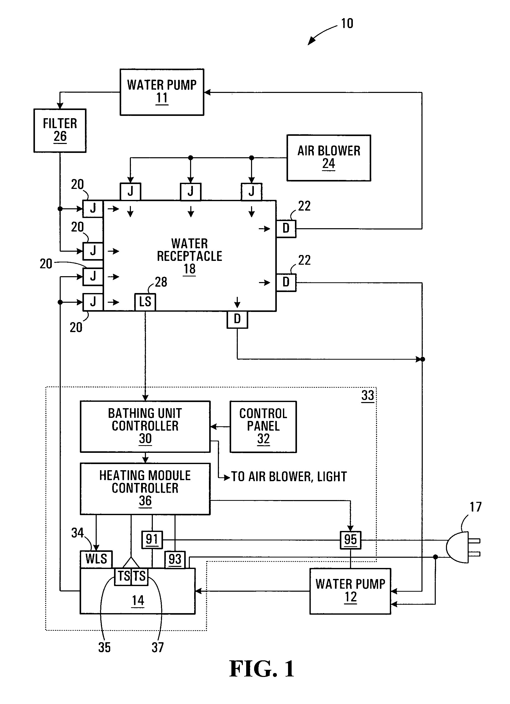
[0029]FIG. 1 illustrates a block diagram of a bathing unit system 10 in accordance with a specific example of implementation of the present invention. It is to be understood that the expressions “bathing unit” and “bathing unit system”, as used for the purposes of the present description, refer to spas, whirlpools, hot tubs, bath tubs, swimming pools and any other type of bathing receptacle that can be equipped with a control system for controlling various operational settings.

[0030]The bathing unit system 10 shown in FIG. 1 includes a water receptacle 18 for holding water, a plurality of jets 20, two water pumps 11&12, a set of drains 22, a heating module 14 and a control system 33. In normal operation, water flows from the water receptacle 18, through a drain 22 and is pumped by water pumps 12 through the heating module 14 where the water is heated. The heated water then leaves the heating module 14 and re-enters the water receptacle 18 through jets 20. This cycle of water leaving...


PUM


Abstract

The present invention provides a control system for a bathing unit that comprises a heating module, a thermal element and a heating module controller. The heating module includes a body that defines a passage through which water can flow, that has an inner surface and an outer surface. The heating module further includes a heating device that is operative for heating the water that flows through the body. The thermal element is mounted to the outer surface of the body such that the thermal element is in thermally conductive communication with water flowing through the body. The heating module controller is operative for obtaining temperature information associated with the thermal element for detecting at least in part on the basis of the temperature information the sufficiency of water flow through the body.

Description

FIELD OF THE INVENTION[0001]The present invention relates to a control system for a bathing unit. More specifically, the present invention relates to a control system for a bathing unit that is operative to detect the sufficiency of water flow through a heating module of the bathing unit.BACKGROUND OF THE INVENTION[0002]Bathing units, such as spas, whirlpools, hot tubs, bathtubs and swimming pools, often include a water holding receptacle, one or more water pumps, a filter system, an air blower, a lighting system, a heating module that includes a heating element, and a control system for activating and managing the various components of the bathing unit.[0003]In use, the water pumps typically circulate the water of the bathing unit through the heating module such that the heating element is able to heat the water flowing through the heating module. The heating element is typically controlled by the control system which selectively activates / deactivates the heating element in order t...

Claims


Application Information

Patent Timeline
Patent Type & Authority Patents(United States)
IPC IPC(8): G05B13/00
CPCA61H33/005A61H33/02F24H9/2028G05D23/1928A61H33/60F24H1/0081A61H33/0087A61H2033/0054A61H33/6068A61H33/601F24H1/54F24H15/128F24H15/25F24H15/238F24H15/395F24H15/212F24H15/421F24H15/246F24H15/37F24H15/335F24H15/407F24H15/196
Inventor GOUGEROT, FLORENTGAUDREAU, DANIELLAFLAMME, BENOITBROCHU, CHRISTIAN
Owner GECKO ALLIANCE GROUP
Why Eureka
Try Eureka