Method and associated device for sensing the air/fuel ratio of an internal combustion engine

a technology of internal combustion engine and air/fuel ratio, which is applied in the direction of electrical control, process and machine control, etc., can solve the problems of a proliferation of sensors, the inability to precisely regulate the on/off the inability to accurately detect the position of lambda sensors, etc., and achieves the effect of convenient implementation

Active Publication Date: 2008-10-21
STMICROELECTRONICS SRL
View PDF8 Cites 19 Cited by
  • Summary
  • Abstract
  • Description
  • Claims
  • Application Information

AI Technical Summary

Benefits of technology

[0038]It has been found a method of sensing the air / fuel ratio in a combustion chamber of an internal combustion engine that may be easily implemented by a respective low-cost device.
[0041]The characteristic parameters to be used for sensing the air / fuel ratio are preferably averaged on a certain number of pressure cycles, for reducing noise and improving the accuracy of the sensing. This certain number of pressure cycles is established by using a clustering algorithm on a data set comprising various moving averages of these parameters carried out on different number of pressure cycles.

Problems solved by technology

Considering that the injection time should ideally be proportional to the air / fuel ratio, these on / off lambda sensors do not allow a precise regulation.
There are lambda sensors that generate a signal representative of the effective value of the air / fuel ratio, but these lambda sensors (the so-called “wide-band lambda sensors”) are either very expensive or not very accurate.
Engines manufacturers are generally reluctant to a proliferation of sensors unless they produce valuable improvements that could not otherwise be attained.
However, it is far from being easy to predict these variations as the engine parameters are varied.
These approaches have important drawbacks.
Unfortunately, this document though establishing that there is only a relationship between the air / fuel ratio and the pressure peak if the LPP parameter of the motor is constant (in particular, if the LPP parameter corresponds to the value for MBT condition), is silent about any possibility of assessing the actual air / fuel ratio as a function of the pressure peak without employing a classic lambda sensor under any condition of operation of the engine.

Method used


Image

  • Method and associated device for sensing the air/fuel ratio of an internal combustion engine
  • Method and associated device for sensing the air/fuel ratio of an internal combustion engine
  • Method and associated device for sensing the air/fuel ratio of an internal combustion engine

Examples


Embodiment Construction

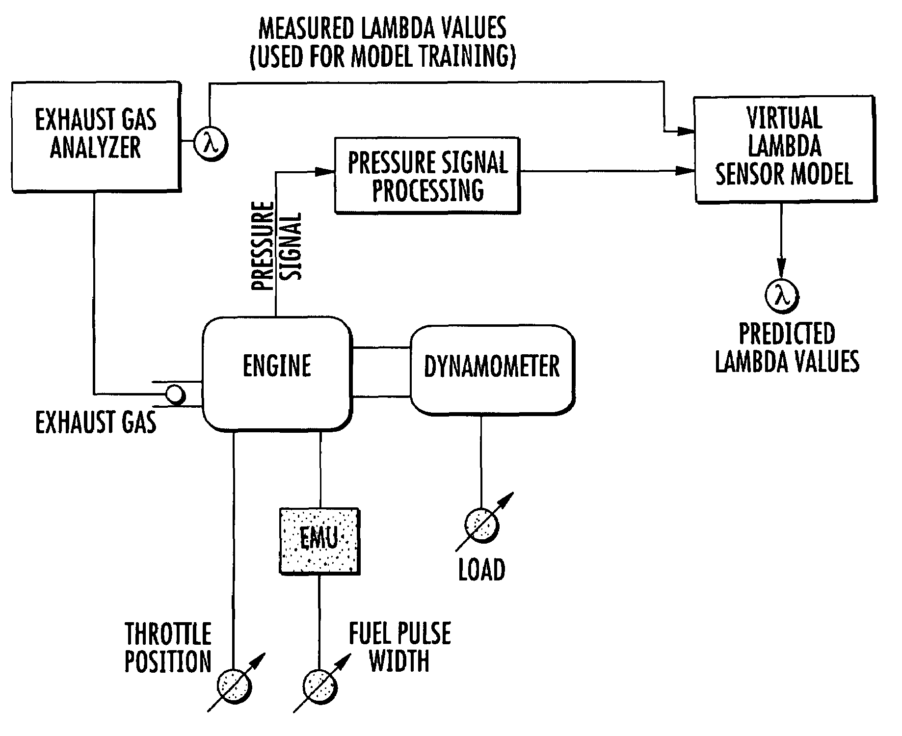
[0086]According to this invention, the inputs for modeling a virtual lambda sensor are obtained from an engine cylinder pressure signal generated by a pressure sensor, such as for instance the integrated pressure sensor disclosed in [21]. According to the invention, a virtual device capable of sensing the air / fuel ratio is based on a learning machine trained according to the scheme of FIG. 9.

[0087]Of course, it is possible to train the learning machine using also characteristics of other signals (the speed of the engine, for instance) in addition to the characteristics of the waveform of the pressure in a cylinder, but surprisingly it has been found that the pressure waveform features alone permit to achieve an outstandingly accurate assessment of the air / fuel ratio.

[0088]Indeed, a wealth of operating parameters of the engine could be extracted from the waveform of pressure in a cylinder. Of course, it is not convenient to consider all of them because the computational load of the l...


PUM

PropertyMeasurementUnit
voltageaaaaaaaaaa
distancesaaaaaaaaaa
temperatureaaaaaaaaaa

Abstract

A method of sensing the air / fuel ratio in a combustion chamber of an internal combustion engine that may be easily implemented by a respective low-cost device includes a pressure sensor and a learning machine that generates a sensing signal representing the air / fuel ratio by processing the waveform of the pressure in at least one cylinder of the engine. In practice, the learning machine extracts characteristic parameters of the waveform of the pressure and as a function of a certain number of them generates the sensing signal.

Description

FIELD OF THE INVENTION[0001]This invention relates to control systems for the operating parameters of internal combustion engines, and, more particularly, to a method and associated device for sensing the air / fuel ratio (briefly AFR) of an internal combustion engine, and an associated control system that uses this sensing device.BACKGROUND OF THE INVENTION[0002]In the last twenty years, fundamental goals of engine manufacturers are to achieve significant reductions of the amounts of pollutants emitted at the engine exhaust, and lower fuel consumption without compromising speed and torque performances. For these reasons, an efficient engine control based on a comprehensive monitoring of the many engine working parameters is desired.[0003]To maintain a strict control of the engine working parameters, Engine Management Systems (EMS) or Engine Control Units (ECU) are used. The EMS implements control strategies which achieve the optimum trade-off between several contradictory objectives:...

Claims


Application Information

Patent Timeline
Patent Type & Authority Patents(United States)
IPC IPC(8): G06F17/00G06F7/00G01L23/22
CPCF02D35/023F02D41/1401F02D41/1405F02D41/1458F02D41/2454G06K9/6223F02D41/1404F02D41/187F02D2041/141G06F18/23213
Inventor CESARIO, NICOLAAMATO, PAOLODI MEGLIO, MAURIZIOPIROZZI, FRANCESCOMOSELLI, GIOVANNITAGLIALATELA-SCAFATI, FERDINANDOCARPENTIERI, FRANCESCO
Owner STMICROELECTRONICS SRL
Why Eureka
Try Eureka