Wringing device

a technology of wringing device and wringing head, which is applied in the field of wringing device, can solve the problems of difficult drainage of high viscosity materials from the bladder, insufficient gravity to drain high viscosity materials, and problems with pumps, etc., and achieve the effect of high viscosity materials

Inactive Publication Date: 2008-10-28
CHEP TECH PTY LTD
View PDF9 Cites 2 Cited by
  • Summary
  • Abstract
  • Description
  • Claims
  • Application Information

AI Technical Summary

Benefits of technology

[0009]Another advantage of this invention is that wringing device provides a constant flow of materials from the flexible container, if desired.

Problems solved by technology

While low viscosity fluids may be easily drained from the bladder, high viscosity materials are difficult to drain from the bladders.
Gravity is often not sufficient to drain high viscosity materials.
Pumps have also been problematic.
In particular, pumps often cavitate and lose prime when attempting to pump high viscosity materials.
In addition, pumps often create voids in the bladder that hampers fluid flow within the bladder.
Conventional systems are also typically fiscally inefficient because conventional systems often leave about two percent of the fluids in the bladder.

Method used


Image

  • Wringing device
  • Wringing device
  • Wringing device

Examples


Embodiment Construction

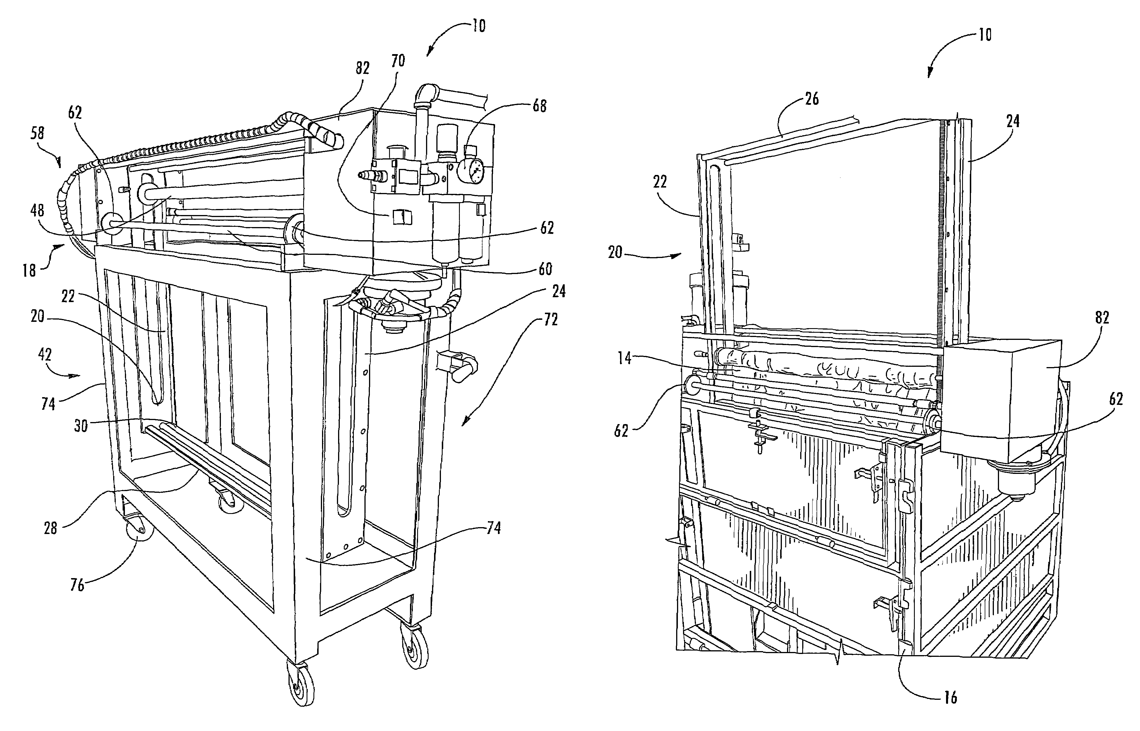
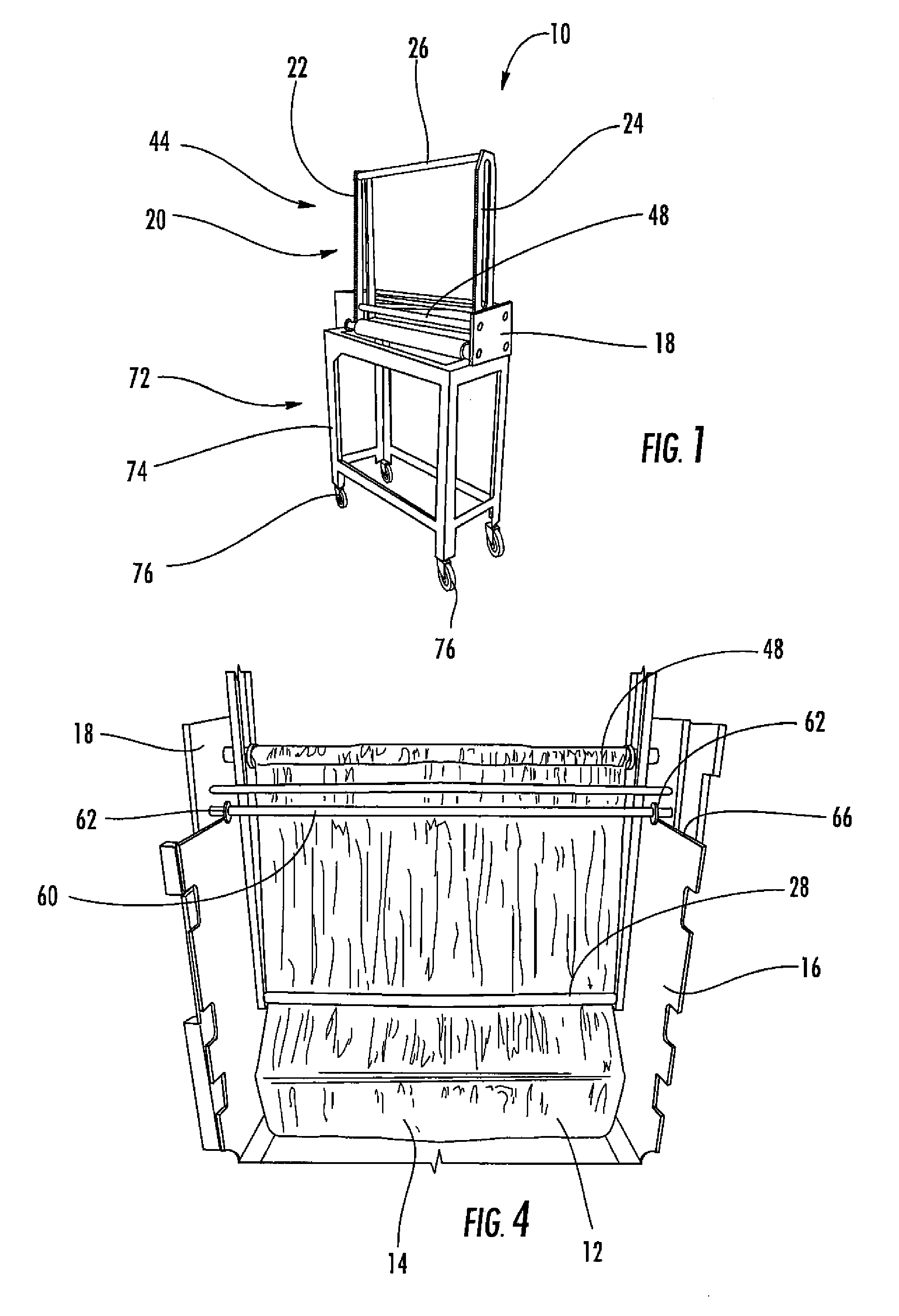
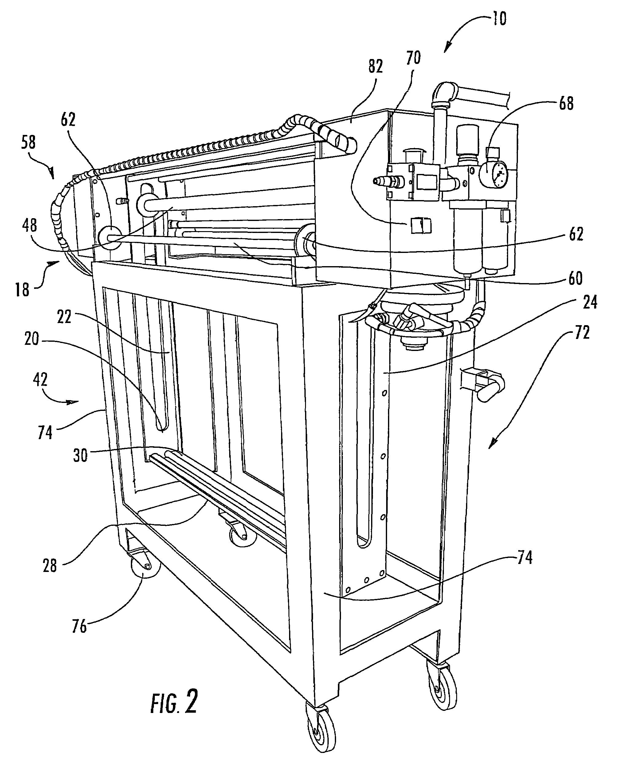
[0019]As shown in FIGS. 1-7, this invention is directed to a wringing device 10 configured to expel materials from a flexible container 14. In particular, as shown in FIG. 4, the wringing device 10 may be configured to expel materials 12, such as, but not limited to fluids, contained within flexible containers 14 by applying forces to the flexible containers 14. The flexible containers 14 may be contained within rigid support structures 16, such as but not limited to, conventional intermediate bulk containers (IBCs) and other appropriate devices.

[0020]As shown in FIG. 1, the wringing device 10 may be formed from a support frame 18 figured to support components of the wringing device 10. The support frame 18 may be configured to support the wringing device 10 while the wringing device 10 is positioned on top of a bulk container, as shown in FIG. 3. The support frame 18 may be formed from any appropriate materials having substantial rigidity to support components of the wringing devic...


PUM


Abstract

A wringing device is used to expel fluids from a flexible container contained within an intermediate bulk container (IBC). The wringing device includes a support frame and a carriage movably coupled to the support frame for supporting components thereof. The wringing device includes a nip shaft coupled to the carriage, and a movable nip shaft movably coupled to the carriage proximate to the nip shaft. The movable nip shaft may be biased toward the nip shaft with a biasing device. The wringing device may include one or more drive devices for driving a take-up shaft and the carriage. The wringing device may also include a transport vehicle for transporting the wringing device between different intermediate bulk containers.

Description

FIELD OF THE INVENTION[0001]This invention is directed generally to wringing devices, and more particularly to devices usable for wringing fluids from flexible containers.BACKGROUND[0002]Fluids and other viscous materials are typically shipped using a variety of shipping containers, such as, drums, tanks, intermediate bulk containers, and others. Intermediate bulk containers are often formed from an external frame configured to support an internal, flexible bladder. The intermediate bulk containers include an inlet fitment on an upper surface of the bladder to fill the bladder and include an exhaust fitment in a lower corner of the flexible bladder to drain the bladder. Intermediate bulk containers are typically drained via gravity or pumps and typically without other assistance. While low viscosity fluids may be easily drained from the bladder, high viscosity materials are difficult to drain from the bladders. Gravity is often not sufficient to drain high viscosity materials. Pumps...

Claims


Application Information

Patent Timeline
Patent Type & Authority Patents(United States)
IPC IPC(8): B30B9/20
CPCB65B69/0075
Inventor NAIDU, VISHNU K.RUSSO, JR., JOSEPH R.
Owner CHEP TECH PTY LTD
Why Eureka
Try Eureka