Dual feedback vacuum fluidics for a flow-type particle analyzer

Active Publication Date: 2012-05-03
BECTON DICKINSON & CO
View PDF27 Cites 20 Cited by
  • Summary
  • Abstract
  • Description
  • Claims
  • Application Information

AI Technical Summary

Benefits of technology

[0020]The modulation of the resistance of the variable-resistance fluidic resistor can be put under automated control using servomechanisms to effect changes in the resistance settings.
[0021]The flow of sample and sheath through the system can be paused to allow, for example, a change to a new sample source after each sample analysis. In the present system, the flow of fluid may be paused by closing a valve situated in the fluid path between the flow cell and the pump. When this valve is closed, the dynamic pressure drop drops to zero, the dynamic feedback loop, which is between the dynamic pressure drop and the pump, is stopped, and the static feedback loop, which is between the static pressure drop and the pump, is activated. The static feedback loop enables maintaining the static pressure drop at a constant l

Problems solved by technology

In general, the design of pressure-driven fluidics systems is more complicated than is the design of vacuum-driven fluidics sy

Method used


Image

  • Dual feedback vacuum fluidics for a flow-type particle analyzer
  • Dual feedback vacuum fluidics for a flow-type particle analyzer
  • Dual feedback vacuum fluidics for a flow-type particle analyzer

Examples


Embodiment Construction

[0029]The following definitions are provided for clarity. Unless otherwise indicated, all terms are used as is common in the art. All reference cited herein, both supra and infra, are incorporated herein by reference.

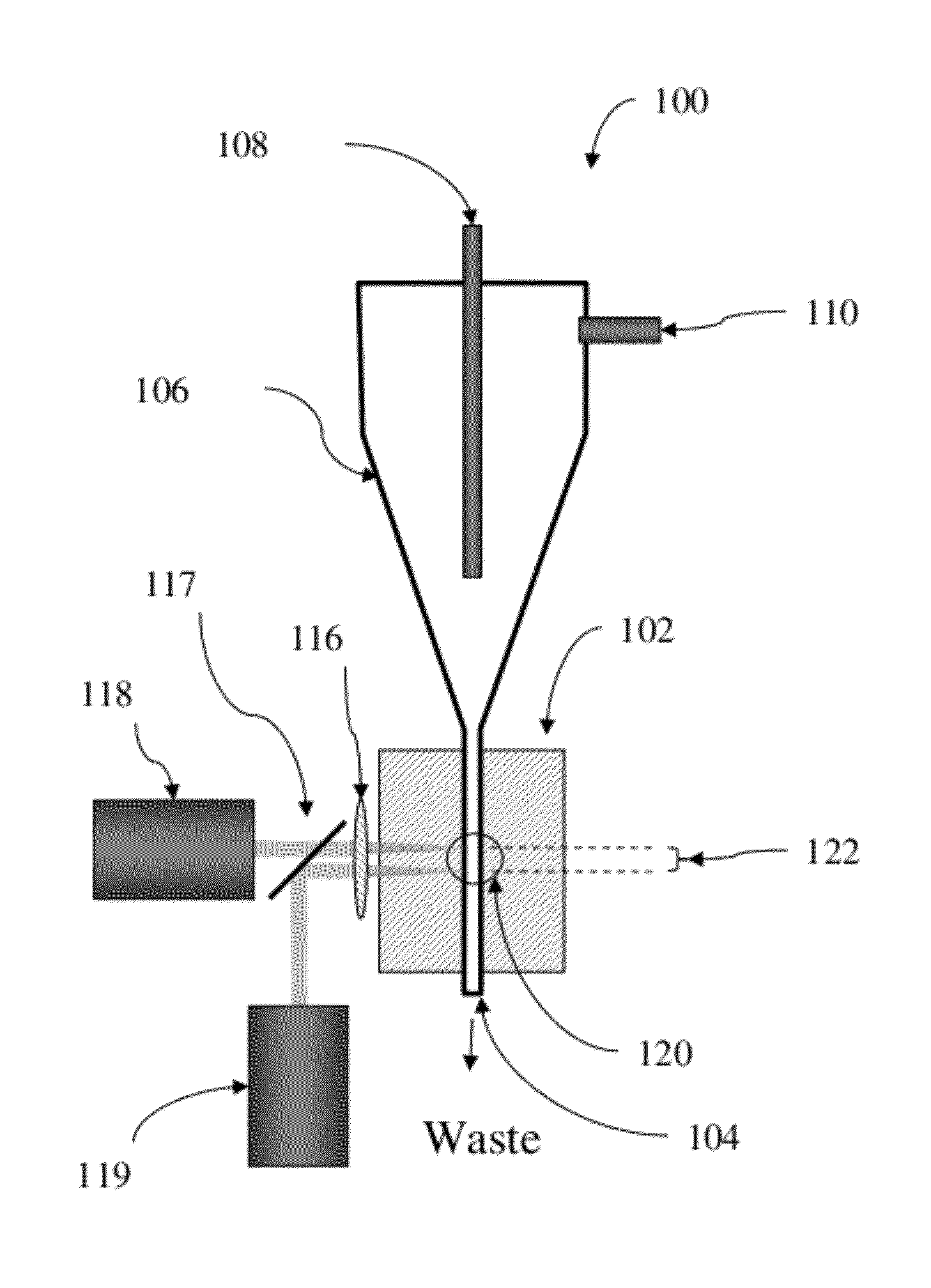
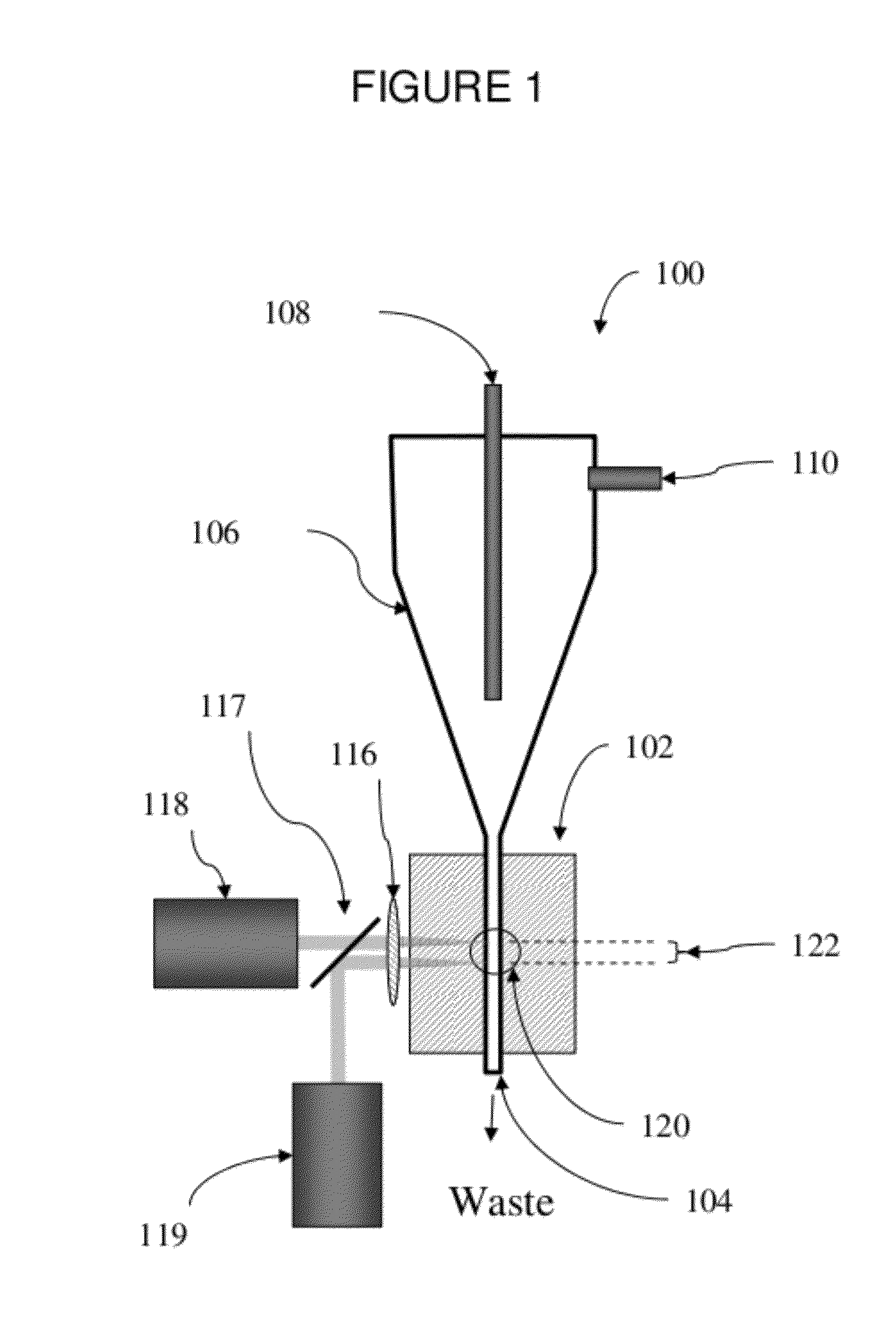
[0030]A “flow-type particle analyzer” is used herein to refers to any instrument that analyzes particles suspended in a flowing fluid stream by passing the particles past one or more optical detectors, and includes, for example, analyzing or sorting flow cytometers, hematology analyzers, and cell counters. A flow-type particle analyzer contains at least two fluid sources, and the two fluid are combined by the system just prior to analysis. For example, a flow cytometer of the present invention analyzes particles suspended in a sample fluid that is hydrodynamically focused by a sheath fluid.

[0031]Sheath fluid refers to a substantially particle-free fluid that is used to surround the particle-containing sample fluid to achieve hydrodynamic focusing, as commonly practiced ...


PUM


Abstract

The present invention relates to a vacuum-driven fluidic system for a flow-type particle analyzer. The system includes a vacuum pump which creates a pressure drop downstream of the flow cell, which pulls sheath fluid and sample fluid through the flow cell. A variable-resistance fluidic resistor is configured to control the ratio of sample fluid flow to sheath fluid flow. Dual feedback circuits, one configured to modulate the vacuum pump power in response to the pressure drop across the flow cell, referred to as the dynamic pressure drop, and a second configured to modulate the vacuum pump power in response to the pressure drop created by the vacuum pump relative to ambient pressure, referred to as the static pressure drop, are used to automatically control the system. The present invention enables adjustment of the sample fluid flow rate while maintaining a constant total fluid flow through the flow cell, and further, enables pausing the system without significant fluctuations in the vacuum.

Description

BACKGROUND OF THE INVENTION[0001]1. Field of the Invention[0002]The present invention relates to instruments for the analysis of particles in a fluid, and their use.[0003]2. Description of Related Art[0004]Flow-type particle analyzers, such as flow cytometers, are well known analytical tools that enable the characterization of particles on the basis of optical parameters such as light scatter and fluorescence, or by electrical properties, such a impedance. In a flow cytometer, for example, particles, such as molecules, analyte-bound beads, or individual cells, in a fluid suspension are passed by a detection region in which the particles are exposed to an excitation light, typically from one or more lasers, and the light scattering and fluorescence properties of the particles are measured. Particles or components thereof typically are labeled with fluorescent dyes to facilitate detection, and a multiplicity of different particles or components may be simultaneously detected by using ...

Claims


Application Information

Patent Timeline
IPC IPC(8): G01N1/24
CPCG01N15/1404G05D16/00G01N2015/1409Y10T137/0379
Inventor VRANE, DAVIDNORTON, PIERCE O.
Owner BECTON DICKINSON & CO
Why Eureka
Try Eureka