Speed control for compressors

a compressor and speed control technology, applied in the direction of motor/generator/converter stopper, dynamo-electric converter control, instruments, etc., can solve the problem of heat damage to the coating of the compressor element and the downstream parts of the compressor, further restriction of the speed range,

Active Publication Date: 2008-10-28
ATLAS COPCO AIRPOWER NV
View PDF7 Cites 34 Cited by
  • Summary
  • Abstract
  • Description
  • Claims
  • Application Information

AI Technical Summary

Problems solved by technology

It is also known that a further restriction of the speed range is imposed by a phenomenon caused by a drastic output reduction of a compressor in the high and low speed range, as a result of which, as the rotational speed of the compressor comes closer to the aforesaid maximum or minimum number of revolutions, the temperature of the compressed gas can raise to such an extent that the coatings of the compressor element and of the downstream parts of the compressor may be damaged by the heat.
A disadvantage of such known compressors with a fixed speed limiter is that the set speed range which is determined on the basis of a worst case scenario, assuming the most adverse circumstances, is in fact too restricting for circumstances which are less adverse, such as for example in case of lower temperatures, allowing in principle for a higher speed range without exceeding the aforesaid maximum critical threshold value of the temperature on the outlet of the compressor element.
This implies that the capacity of such a compressor cannot be used to the full as far as the delivered gas flow is concerned in circumstances which deviate from the aforesaid worst case scenario.

Method used


Image

  • Speed control for compressors
  • Speed control for compressors
  • Speed control for compressors

Examples


Embodiment Construction

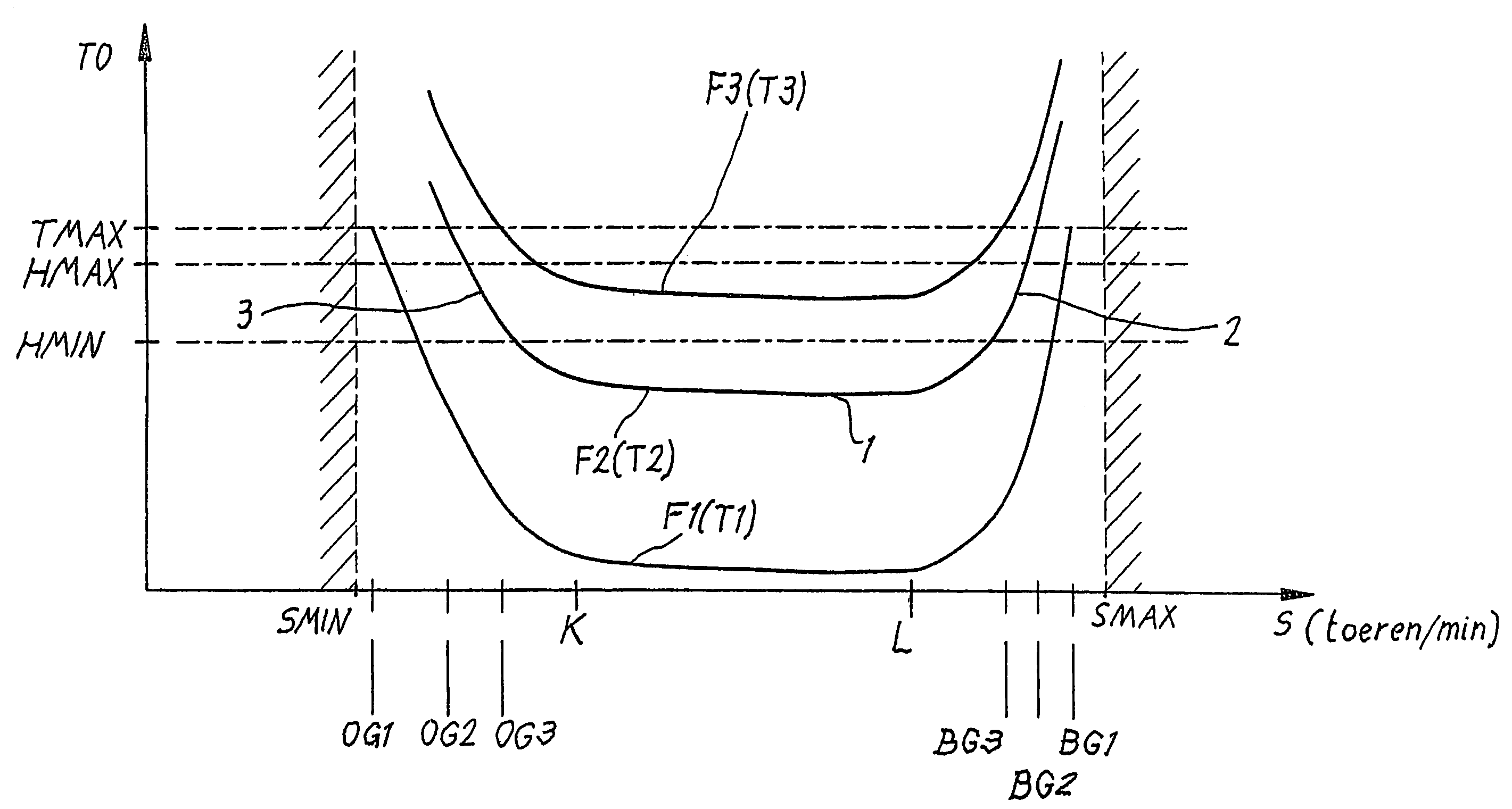
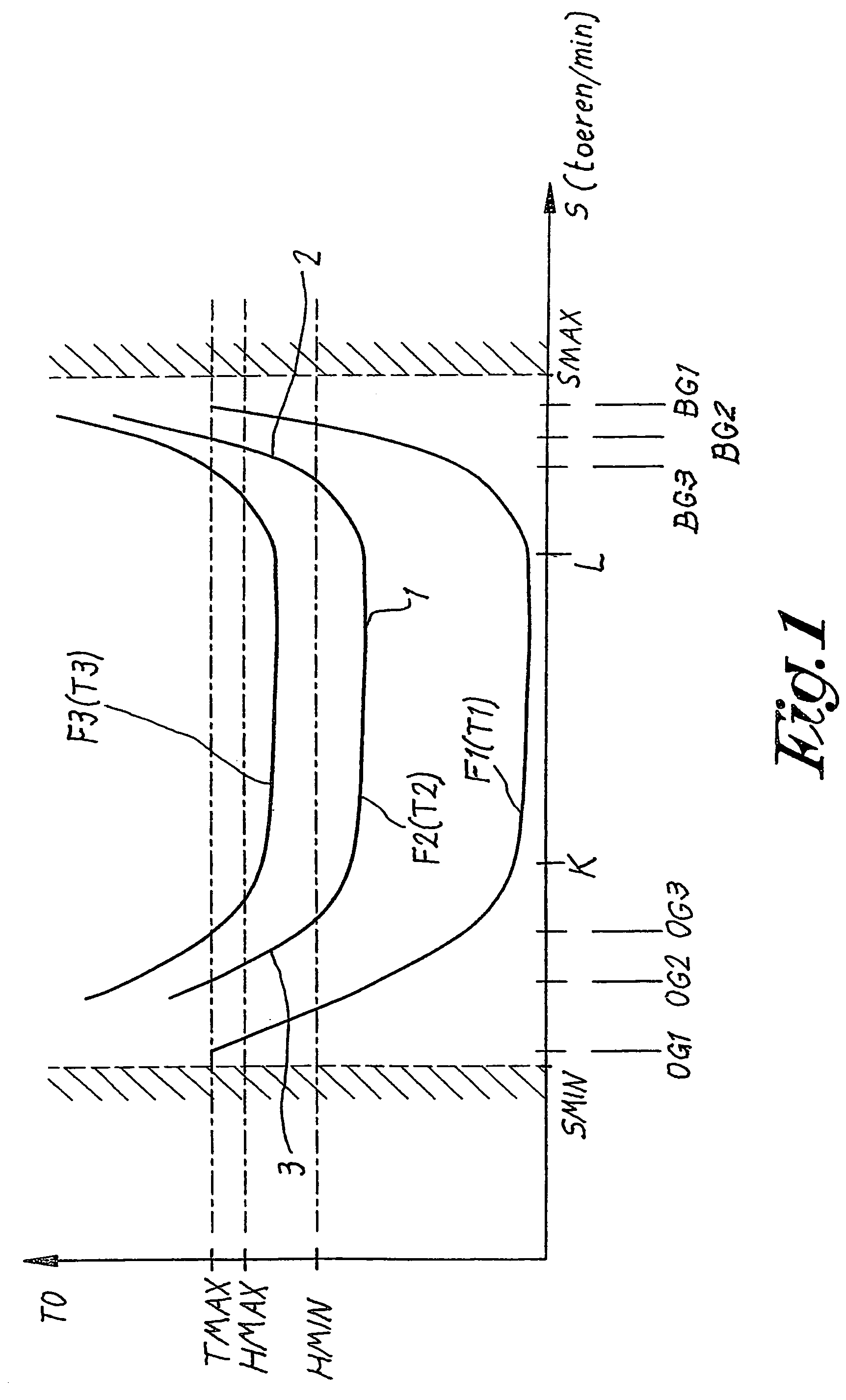
[0023]FIG. 1 shows the temperature curve TO of the compressed gas on the outlet of the compressor element of a conventional compressor as a function of the number of revolutions S of the compressor, such for an admitted maximum speed range which is limited by an admitted minimum rotational speed SMIN and an admitted maximum rotational speed SMAX, whereby SMIN and SMAX are determined among others by the limits of the rotating parts.

[0024]FIG. 1 shows three outlet temperature curves, F1, F2 and F3 respectively, represented for three different ambient temperatures, namely a low temperature T1, a higher temperature T2 and a still higher temperature T3.

[0025]As can be clearly derived from this FIG. 1, each curve F1-F2-F3 has an almost flat middle part 1 with an almost constant outlet temperature for an ambient temperature that remains the same and two steeper parts, a part 2 in the high speed range of the compressor close to SMAX and a part 3 in the lower speed range close to SMIN respec...


PUM


Abstract

Improvements to a compressor which consists in that, as soon as the measured outlet temperature (TO) reaches a certain hysteresis upper temperature limit (HMAX), the actual rotational speed of the compressor element is either lowered with a speed jump (DS) when the measured rotational speed is situated in the higher speed range close to the maximum rotational speed (SMAX), or is increased with a speed jump (DS) when the measured rotational speed is situated in the lower speed range close to the minimum rotational speed (SMIN).

Description

BACKGROUND OF THE INVENTION[0001]1. Field of the Invention[0002]The present invention concerns some improvements to compressors.[0003]2. Description of Related Art[0004]In particular, the present invention concerns a compressor for compressing gases of the type comprising at least one compressor element with a gas outlet and a gas inlet, as well as a sensor to determine the outlet temperature in the gas outlet, a sensor to determine the rotational speed of the compressor element, a motor with an electronically adjustable speed driving this compressor element, and finally a control device for said motor.[0005]It is known that such compressors can operate within a specific maximum speed range of the number of revolutions, between a maximum and a minimum number of revolutions which depends among others on the mechanical limitations of the rotating parts, whereby irrevocable damage can be caused to the compressor in case the number of revolutions exceeds said speed range.[0006]The speed...

Claims


Application Information

Patent Timeline
Patent Type & Authority Patents(United States)
IPC IPC(8): F04B49/00F04B49/02F04B49/10F04C28/08F04C28/00F04C29/00
CPCF04B49/103F04C28/00F04C28/08F04C2270/19
Inventor MOENS, ERIK ERIC DANIEL
Owner ATLAS COPCO AIRPOWER NV
Why Eureka
Try Eureka