
Method and an apparatus for measuring the performance of antennas, mobile phones and other wireless terminals

Inactive Publication Date: 2008-10-28
BLUETEST
View PDF22 Cites 37 Cited by
  • Summary
  • Abstract
  • Description
  • Claims
  • Application Information

AI Technical Summary

Benefits of technology

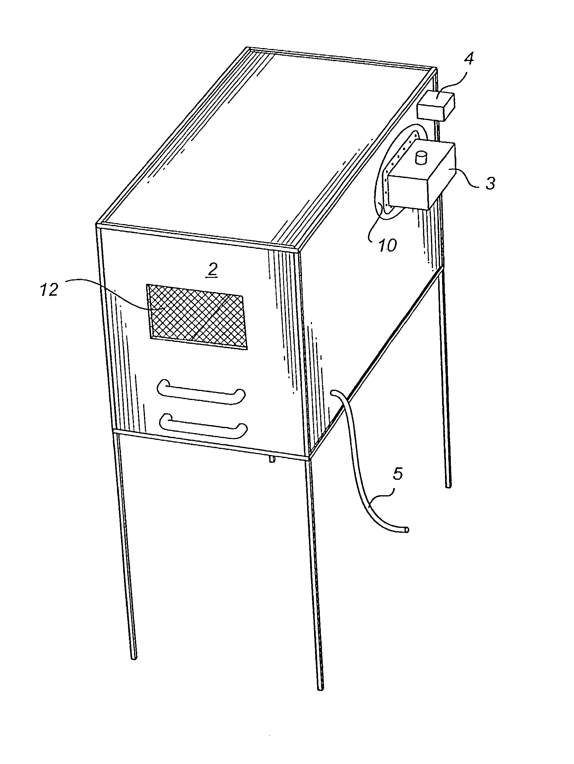
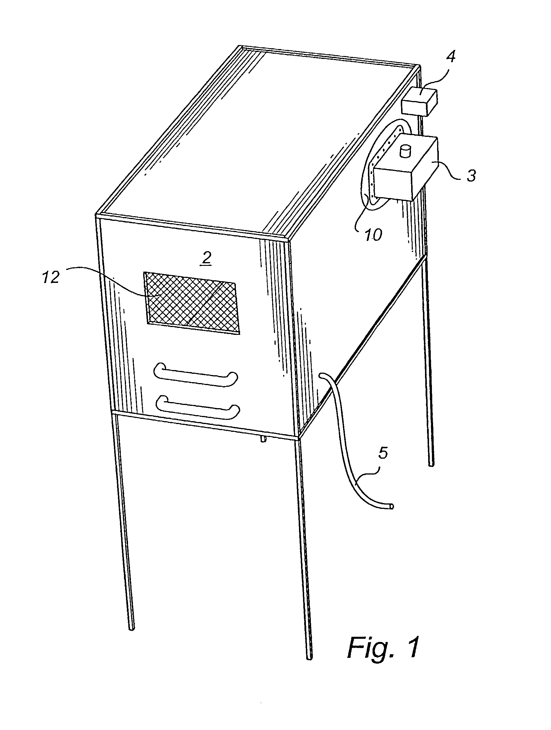
[0011]More specifically, an embodiment of the invention relates to an apparatus and instrument set-up for measuring the radiation efficiency of antennas or the communication power (CP) of mobile and wireless terminals such as mobile phones. Compared to e.g. a standard antenna measurement range, an embodiment of the invention is cheaper and requires much less space and effort. The measurements can also be done much faster, and the accuracy is high.
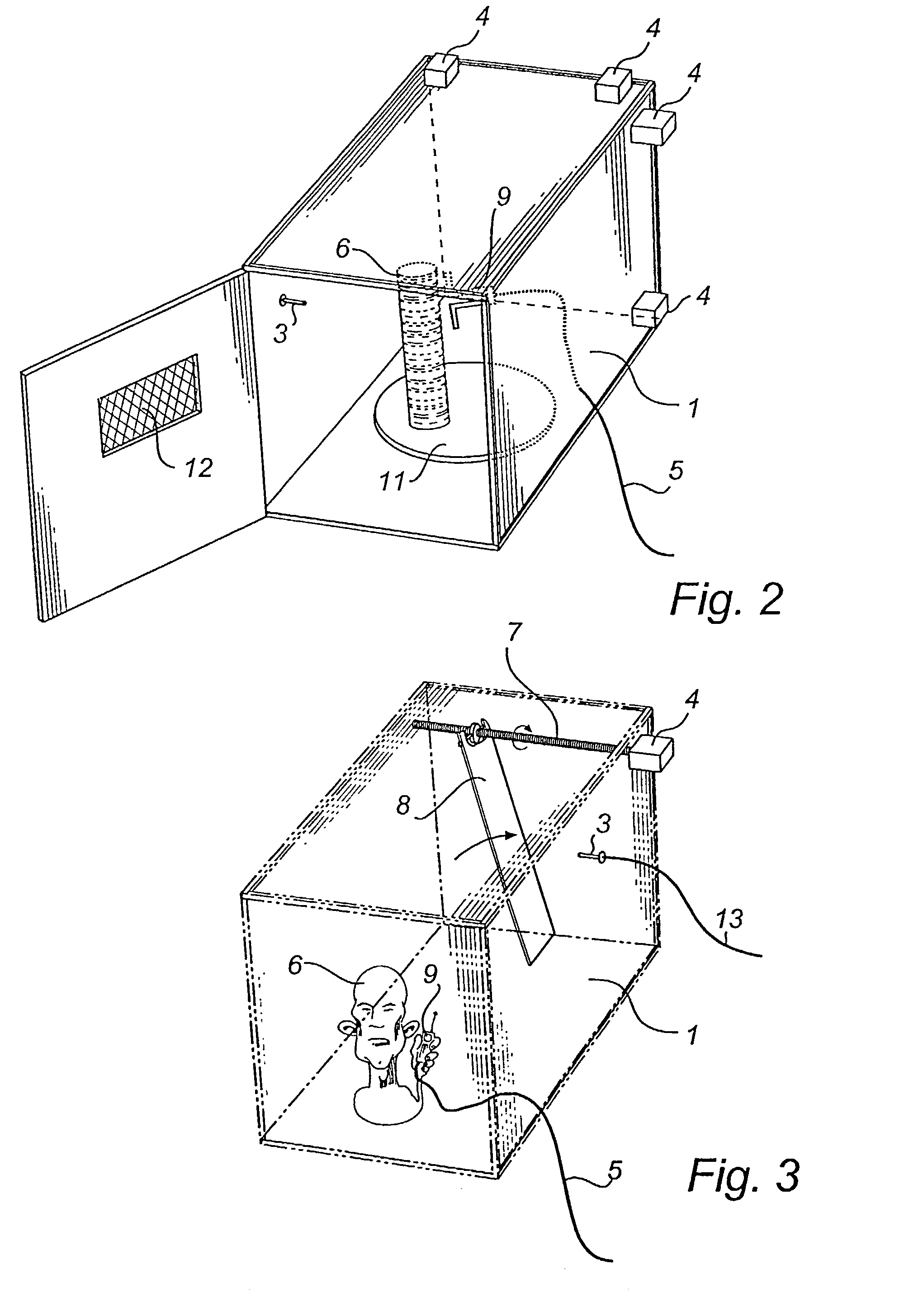
[0031]When measuring CP, we are not able to remove the error due to the direct coupling between the FA and the antenna of the TUT. However, it is a fact that this error is larger the more the chamber is loaded with lossy material. Therefore, we may improve the accuracy of a CP measurement by reducing the size of the head phantom, e.g. by cutting it in two halves and using one of them at the time.

Problems solved by technology

This traditional measurement set-up requires expensive equipment, much work, and the final result is obtained after a long measurement procedure.
In addition, the measured radiation patterns are not of much interest for terminal antennas.
This is very time-consuming and expensive with traditional radiation pattern measurements.
Similar problems as related above are encountered when measuring the total radiated power from the whole mobile or wireless terminal, such as from a mobile phone.
Further, it is a problem with known measuring equipment to make a quick, easy and / or reliable estimation of the absorption of electromagnetic radiation in the human body.
Existing equipment that is used to measure radiation into the human body is very expensive and laborious to use.

Method used


Image

  • Method and an apparatus for measuring the performance of antennas, mobile phones and other wireless terminals
  • Method and an apparatus for measuring the performance of antennas, mobile phones and other wireless terminals
  • Method and an apparatus for measuring the performance of antennas, mobile phones and other wireless terminals

Examples


Embodiment Construction

[0010]It is therefore the object of an embodiment of the invention to provide an apparatus and method for measuring the performance of antennas as well as of complete mobile and wireless terminals, such as mobile phones, at least partly solving the problems encountered in the prior art. Further, it is an object of an embodiment of the present invention to provide an apparatus and method for measuring absorbed radiation.

[0011]More specifically, an embodiment of the invention relates to an apparatus and instrument set-up for measuring the radiation efficiency of antennas or the communication power (CP) of mobile and wireless terminals such as mobile phones. Compared to e.g. a standard antenna measurement range, an embodiment of the invention is cheaper and requires much less space and effort. The measurements can also be done much faster, and the accuracy is high.

[0012]An embodiment of the invention relates to a chamber with reflecting walls. We use here the word wall to describe side...


PUM


Abstract

An apparatus and a method are for measuring the radiation efficiency of antennas and the communication power of mobile and wireless terminals. The apparatus includes a chamber to enclose the antenna or terminal to be tested. The chamber includes walls of an inwardly reflective material, rendering the walls reflective to electromagnetic waves. The quality of the antenna or terminal is obtained by averaging the power transmitted between the antenna under test and a fixed antenna, or the power received at the fixed antenna when the terminal under test is used as a transmitter. The averaging is done over the measured power for several different positions of moving objects in the chamber and of a moving platform on which the antenna or terminal under test is located. The radiation efficiency or communication power is obtained by relating the measured average levels to those of a reference antenna or a reference terminal of known radiation efficiency or communication power.

Description

[0001]This application is the national phase under 35 U.S.C. § 371 of PCT International Application No. PCT / SE01 / 00422 which has an International filing date of Feb. 26, 2001, which designated the United States of America and which claims priority on Swedish Patent Application numbers SE 0001158-5 filed Mar. 31, 2000 and SE 0002980-1 filed Aug. 23, 2000, the entire contents of which are hereby incorporated herein by reference.BACKGROUND OF THE INVENTION[0002]Mobile and wireless telephony has grown enormously the last years, and it is expected to continue to grow all over the world. In addition, more and more services are added to the mobile phones, such as access to Internet. In a mobile communication system the mobile phones are terminals, and the network is formed by wireless connection of each terminal to the nearest fixed base station, where the base stations are connected together with other base stations in a fixed network. The next years we will also see a rapid growth of sho...

Claims


Application Information

Patent Timeline
IPC IPC(8): G06F11/30G01R29/10G01R29/08G01R31/28G01R31/317H04B17/00
CPCG01R29/0821G01R29/105
Inventor KILDAL, PER-SIMON
Owner BLUETEST
Learn More