Micromachined comb capacitive accelerometer

a capacitive accelerometer and micro-machined comb technology, applied in acceleration measurement, measurement devices, instruments, etc., can solve the problems of significant risk of accelerometer malfunction, accumulation of electrical charge on the surface of sensitive fingers, and substantial drop in production yield

Active Publication Date: 2008-11-04
COMMISSARIAT A LENERGIE ATOMIQUE ET AUX ENERGIES ALTERNATIVES
View PDF6 Cites 15 Cited by
  • Summary
  • Abstract
  • Description
  • Claims
  • Application Information

AI Technical Summary

Benefits of technology

[0012]This disposition helps to increase the rigidity of the ensemble of the mobile fingers and / or the fixed fingers in the zone where the mobile fingers are strongly displaced.
[0015]Advantageously, the mobile mass comprises at least one connecting beam etched in the substrate. The effect of the local thickening of the mobile mass is to increase the sensitivity of the accelerometer without increasing its size.
[0016]In an advantageous embodiment of the invention the mobile fingers and / or the fixed fingers located at the ends of the mobile mass have a width greater than that of the other mobile and / or fixed fingers. This allows the rigidity of the ensemble of the fingers to be increased, without limiting their number.

Problems solved by technology

A problem of accelerometers of the prior art described hereinabove originates from the fact that under certain conditions the mobile fingers and the fixed fingers stay stuck to one another, as illustrated in FIG. 1, resulting in a substantial drop in production yield, and to significant risk of malfunction of the accelerometer.
This problem could originate with the accumulation of electrical charge on the surfaces of the sensitive fingers and occurs either after a shock, or after the application of a voltage between fixed combs and mobile combs capable of putting the two sets of electrodes in contact.
This solution is complex because, on the one hand, it is difficult to obtain a thick sacrificial layer, and on the other hand, using a non-stressed layer limits the choice of material and requires a high-temperature process to be utilised.

Method used


Image

  • Micromachined comb capacitive accelerometer
  • Micromachined comb capacitive accelerometer
  • Micromachined comb capacitive accelerometer

Examples


Embodiment Construction

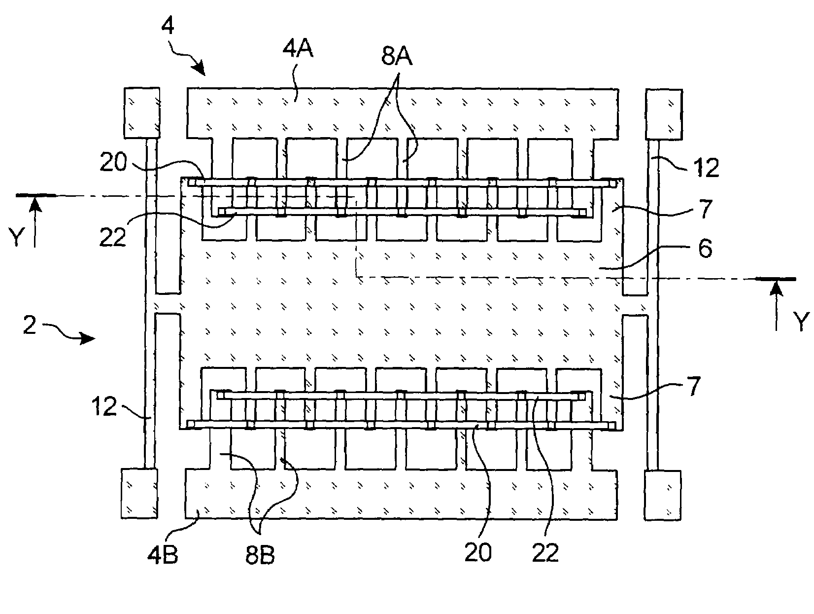
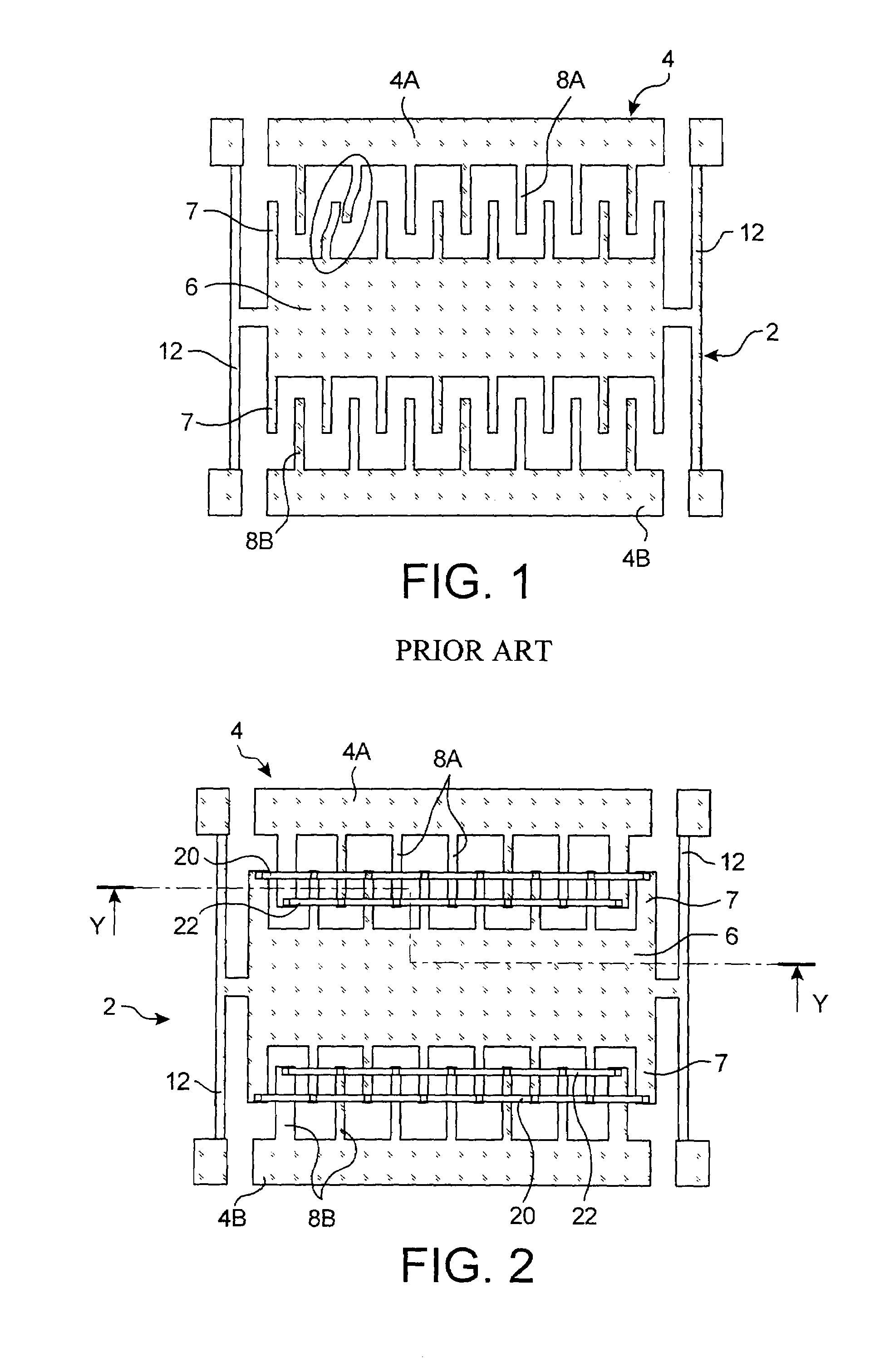
[0009]The invention recommends a comb capacitive accelerometer comprising a substrate, a mobile electrode relative to said substrate fitted with an ensemble of mobile fingers, a fixed electrode relative to said substrate fitted with an ensemble of fixed fingers, each of said mobile fingers being positioned between two contiguous fixed fingers so as to form a microstructure with interdigital combs.

[0010]According to the present invention, the mobile fingers are connected to one another by at least a first connecting beam etched directly in the substrate, and / or, the fixed fingers are connected to one another by at least a second connecting beam etched directly into the substrate.

[0011]Said connecting beams are preferably located in the vicinity of the end of the fingers to be connected.

[0012]This disposition helps to increase the rigidity of the ensemble of the mobile fingers and / or the fixed fingers in the zone where the mobile fingers are strongly displaced.

[0013]Advantageously, th...


PUM


Abstract

A comb capacitive accelerometer comprising a substrate, a mobile electrode relative to said substrate fitted with a plurality of mobile fingers, an electrode fixed relative to said substrate fitted with a plurality of fixed fingers, each of said mobile fingers being positioned between two contiguous fixed fingers so as to form a microstructure with interdigital combs. According to the invention the mobile fingers are connected to one another by at least a first connecting beam etched directly into the substrate, and / or the fixed fingers are connected to one another by at least a second connecting beam etched directly in the substrate.

Description

TECHNICAL FIELD[0001]The invention relates to the field of silicon micro-sensors and more specifically concerns a micromachined comb capacitive accelerometer comprising a substrate, a mobile electrode relative to said substrate fitted with an ensemble of sensitive mobile fingers, a fixed electrode relative to said substrate fitted with an ensemble of fixed sensitive fingers, each of the mobile fingers being positioned between two contiguous fixed fingers so as to form a microstructure with interdigital combs.STATE OF PRIOR ART[0002]FIG. 1 schematically illustrates a plan view of an accelerometer with interdigital combs of the prior art comprising a first electrode 2 and a second electrode 4 etched in the same silicon substrate 5. The first electrode 2 is constituted by a mobile mass 6 fitted with a plurality of mobile fingers 7 extending laterally. The second electrode is composed of two parts 4A, 4B located on either side of the mobile mass 6 and each comprising several fixed finge...

Claims


Application Information

Patent Timeline
Patent Type & Authority Patents(United States)
IPC IPC(8): G01P15/125
CPCB81B3/007G01P15/0802G01P15/125B81B2201/0235B81B2203/0136
Inventor ROBERT, PHILIPPE
Owner COMMISSARIAT A LENERGIE ATOMIQUE ET AUX ENERGIES ALTERNATIVES
Why Eureka
Try Eureka